Weight balancing mechanism for operation microscope stand

a technology of weight balancing mechanism and operation microscope, which is applied in the direction of surgical instrument support, application, instruments, etc., can solve problems such as complicated operations

Inactive Publication Date: 2009-01-06
MITAKA KOHKI
View PDF11 Cites 19 Cited by
  • Summary
  • Abstract
  • Description
  • Claims
  • Application Information

AI Technical Summary

Problems solved by technology

In this related art, however, since both the weight balancing operation for the main parallel linkage and the weight balancing operation for the supplemental parallel linkage are performed by pressing the weight balancing switch provided on the operating panel, an operator, when he or she only wants to correct a slightly unbalanced state of the supplemental parallel linkage in a short period of time during surgery, has to perform an overall weight balancing operation, resulting in a complicated operation.

Method used


Image

  • Weight balancing mechanism for operation microscope stand
  • Weight balancing mechanism for operation microscope stand
  • Weight balancing mechanism for operation microscope stand

Examples


Embodiment Construction

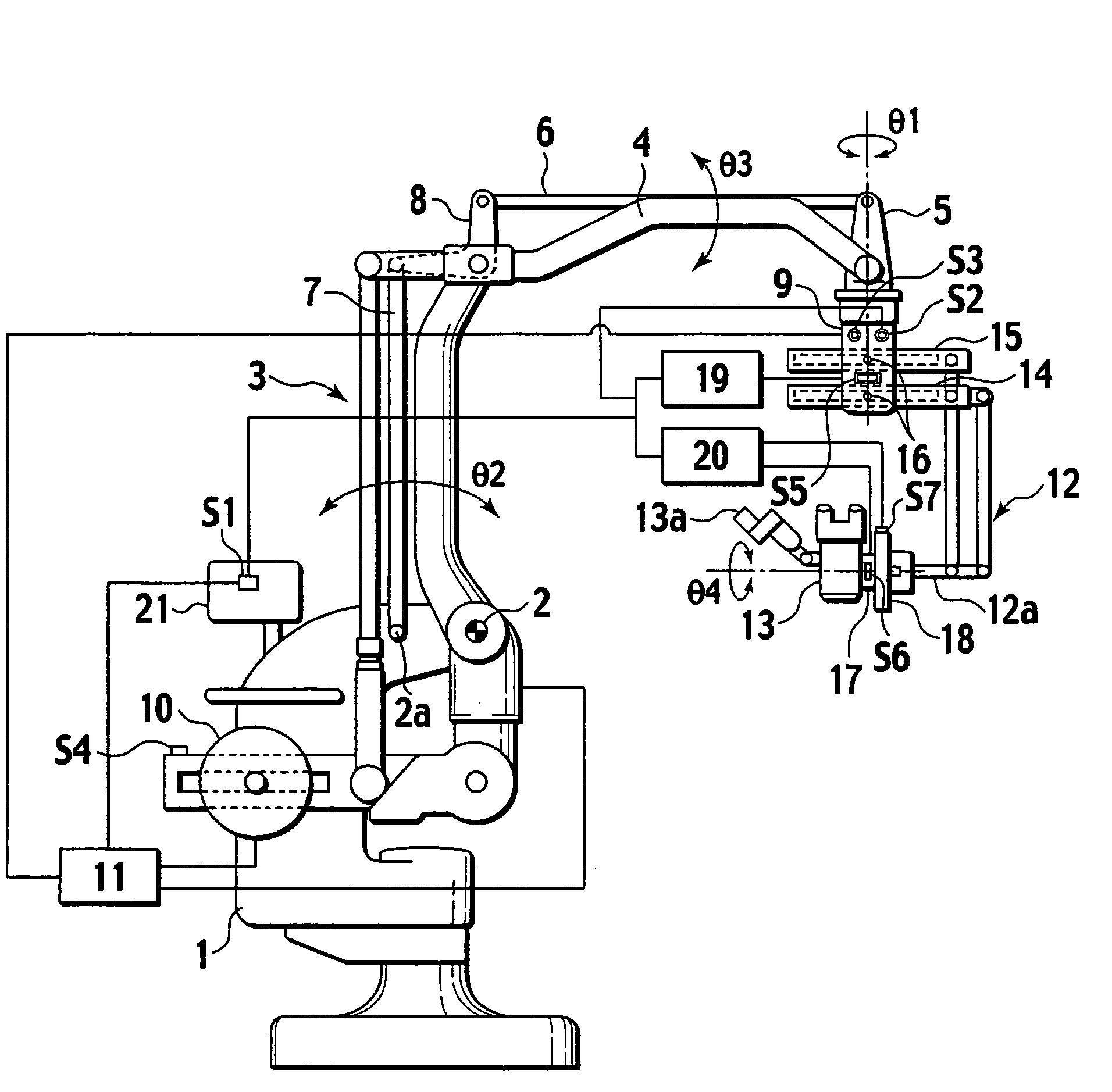
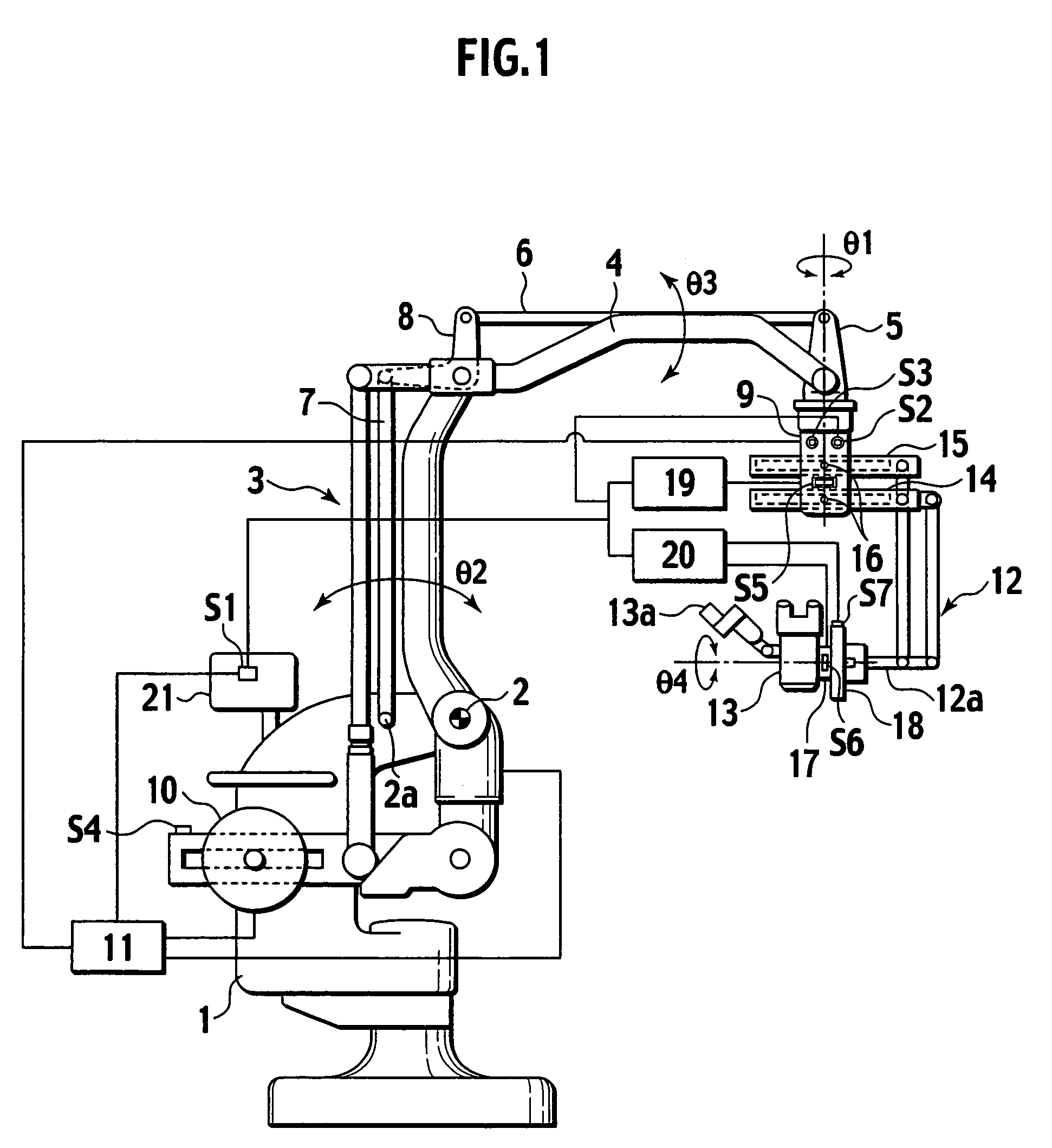
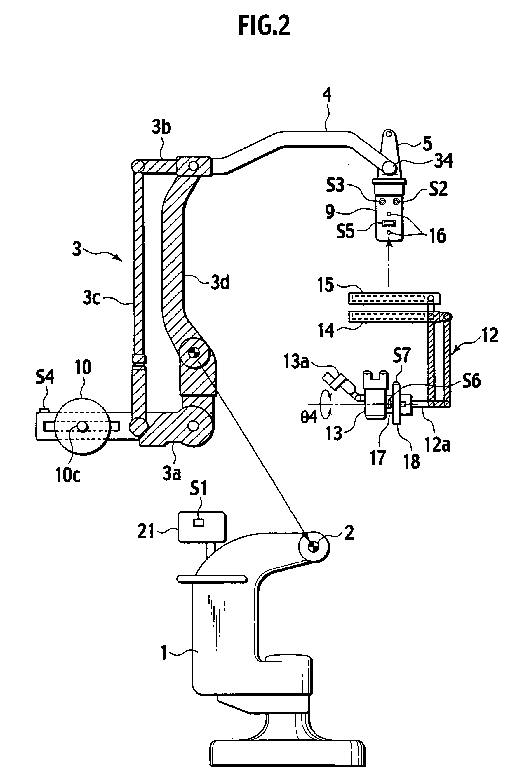
[0027]A preferred embodiment of the present invention will be described with reference to FIGS. 1 to 14. A stand body 1 is installed on the floor in an operating room. A rotation axis 2 is fixed relative to the stand body 1 and positions parallel to a horizontal plane. A main parallel linkage 3 (see a shaded portion in FIG. 2) is rotatably supported on the rotation axis 2 at its vertically intermediate portion.

[0028]The main parallel linkage 3 includes four link elements 3a, 3b, 3c and 3d. The link element 3b constituting the upper link is extended to form a support arm 4. A distal link 5 is provided via a rotation axis 34 at the distal end of the support arm 4 which is relatively fixed to the upper link 3b. The rotation axis 34 always positions parallel to a horizontal plane. The distal link 5 is connected at its upper end to the stand body 1 via two sub-arms 6 and 7 and an L-shaped crank lever 8. Thus, another parallel linkage with a link element 2-2a being fixed to the stand body...


PUM


Abstract

A first switch for performing both a weight balancing operation for a main parallel linkage and a weight balancing operation for a supplemental parallel linkage is provided separately from a second switch for only performing a weight balancing operation for the supplemental parallel linkage. An operator can press the second switch during surgery to only correct a slightly unbalanced state of the supplemental parallel linkage in a short period of time, resulting in increased operability of the operation microscope. While the first switch is provided on an operating panel at a stand body, the second switch is provided at a lower part of a distal link located above an operating space for the operation microscope. It is thus easy for an operator to press the second switch during surgery.

Description

BACKGROUND OF THE INVENTION[0001]1. Field of the Invention[0002]This invention relates to weight balancing mechanisms for a stand supporting an operation microscope.[0003]2. Description of the Related Art[0004]An operation microscope stand is known as a structure in which a main parallel linkage is rotatably supported on a rotation axis provided on a stand body which is installed on the floor or the ceiling; an operation microscope is supported via a supplemental parallel linkage at a distal end of a support arm which is an extension of the upper link of the main parallel linkage; and a counterweight is supported at an extension of the lower link of the first parallel linkage.[0005]This operation microscope stand allows the main parallel linkage to be held at a desired position by bringing the mass center of the main parallel linkage and all the structures it supports in agreement with the rotation axis, using the counterweight for weight balancing on the rotation axis.[0006]The ope...

Claims


Application Information

Patent Timeline
Patent Type & Authority Patents(United States)
IPC IPC(8): A47F7/00A61B19/00F16M11/04F16M11/12G02B7/00G02B21/00
CPCA61B19/26F16M11/04F16M11/105F16M11/12F16M11/2064G02B7/001A61B2019/264A61B2019/265F16M2200/044A61B90/50A61B2090/504A61B2090/506
Inventor NAKAMURA, KATSUSHIGE
Owner MITAKA KOHKI
Why Eureka
Try Eureka