Electrical switching apparatus, and movable contact assembly and contact spring assembly therefor

a technology of electrical switching apparatus and movable contact assembly, which is applied in the direction of circuit-breaking switch, snap-action arrangement, contact mechanism, etc., can solve the problems of consuming valuable space, affecting the operation of electrical switching apparatus, and being relatively difficult to assembl

Active Publication Date: 2009-01-06
EATON INTELLIGENT POWER LTD
View PDF15 Cites 14 Cited by
  • Summary
  • Abstract
  • Description
  • Claims
  • Application Information

AI Technical Summary

Benefits of technology

[0016]The first and second contact spring housing members may be substantially identical, and they may each comprise at least one protrusion and at least one aperture, wherein the first contact spring housing member and the second contact spring housing member are positioned in order that the protrusion of the first contact spring housing member engages the aperture of the second contact spring housing member, and the protrusion of the second contact spring housing member engages the aperture of the first contact spring housing member, thereby securing the contact spring assembly together.

Problems solved by technology

Among the disadvantages of such contact spring assemblies is that they are relatively complex in design, employing a relatively large number of springs (e.g., at least one set of eight or more springs), and comprising a unit which is separate from, and disposed beside (i.e., behind and / or adjacent to), the contact arm carrier.
As a result, the contact spring assembly not only consumes valuable space within the circuit breaker housing, it is also relatively difficult to assemble.
Moreover, the large size and inconvenient location of the contact spring assembly reduces the dimension within the circuit breaker housing which is available to accommodate the motion of the movable contact assembly during the various stages (e.g., opening; closing; tripping open in response to a fault condition) of its operation.
It also adds mass, which decreases the opening velocity of the movable contact assembly, thus adversely affecting the circuit interruption performance of the circuit breaker.
A still further disadvantage is the fact that contact pressure is not provided separately to each individual contact arm or finger of the movable contact assembly.

Method used


Image

  • Electrical switching apparatus, and movable contact assembly and contact spring assembly therefor
  • Electrical switching apparatus, and movable contact assembly and contact spring assembly therefor
  • Electrical switching apparatus, and movable contact assembly and contact spring assembly therefor

Examples


Embodiment Construction

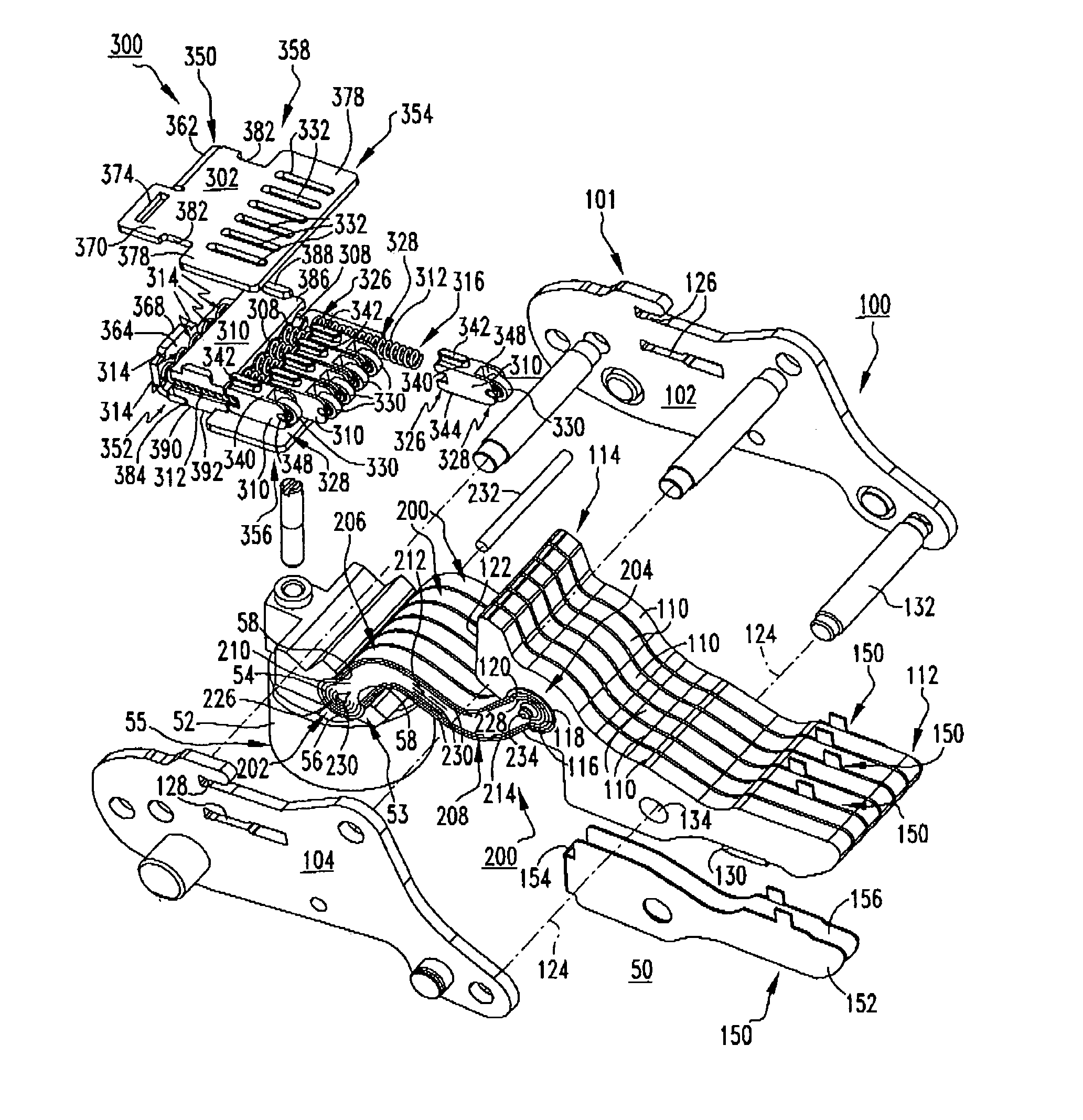
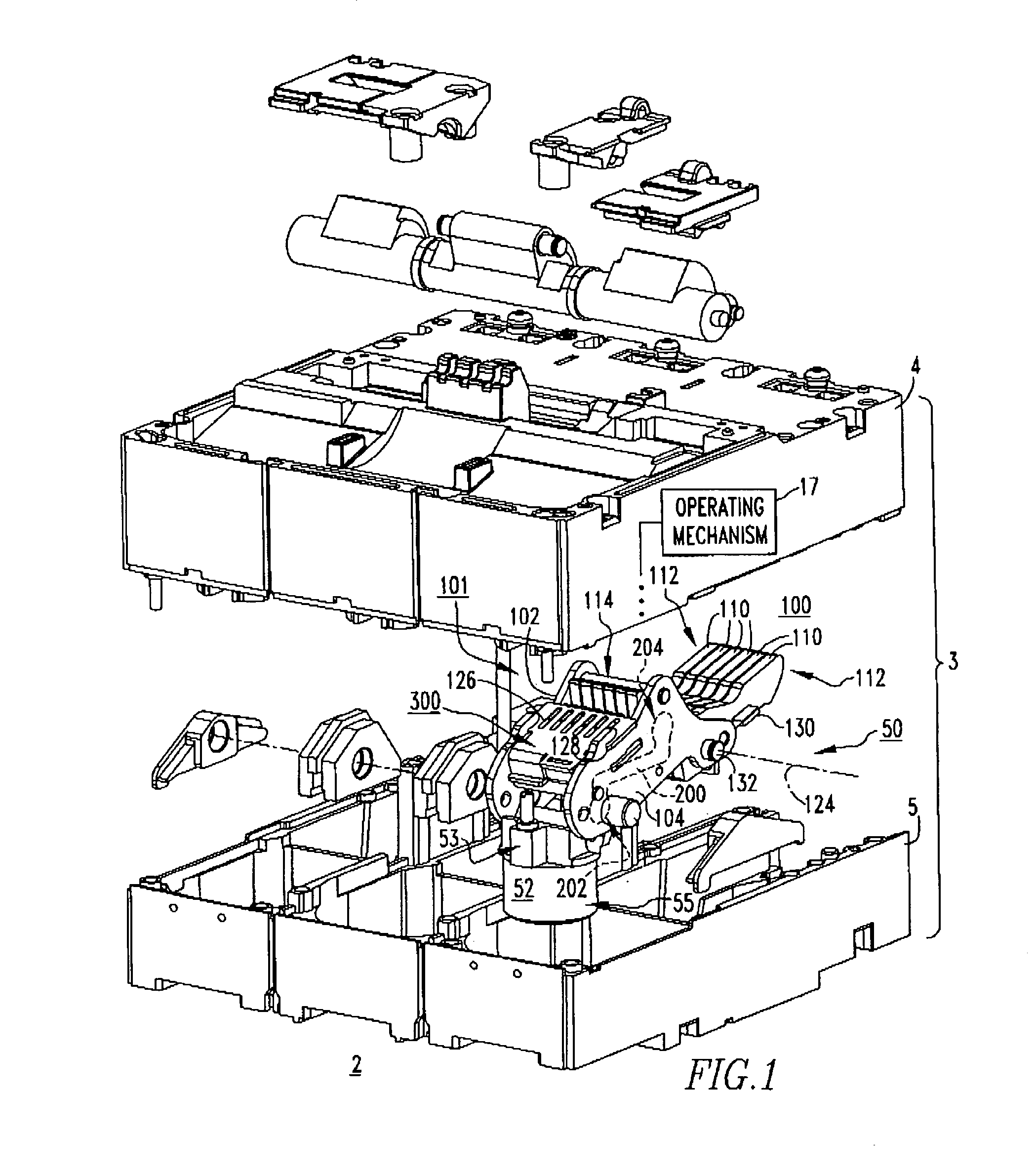
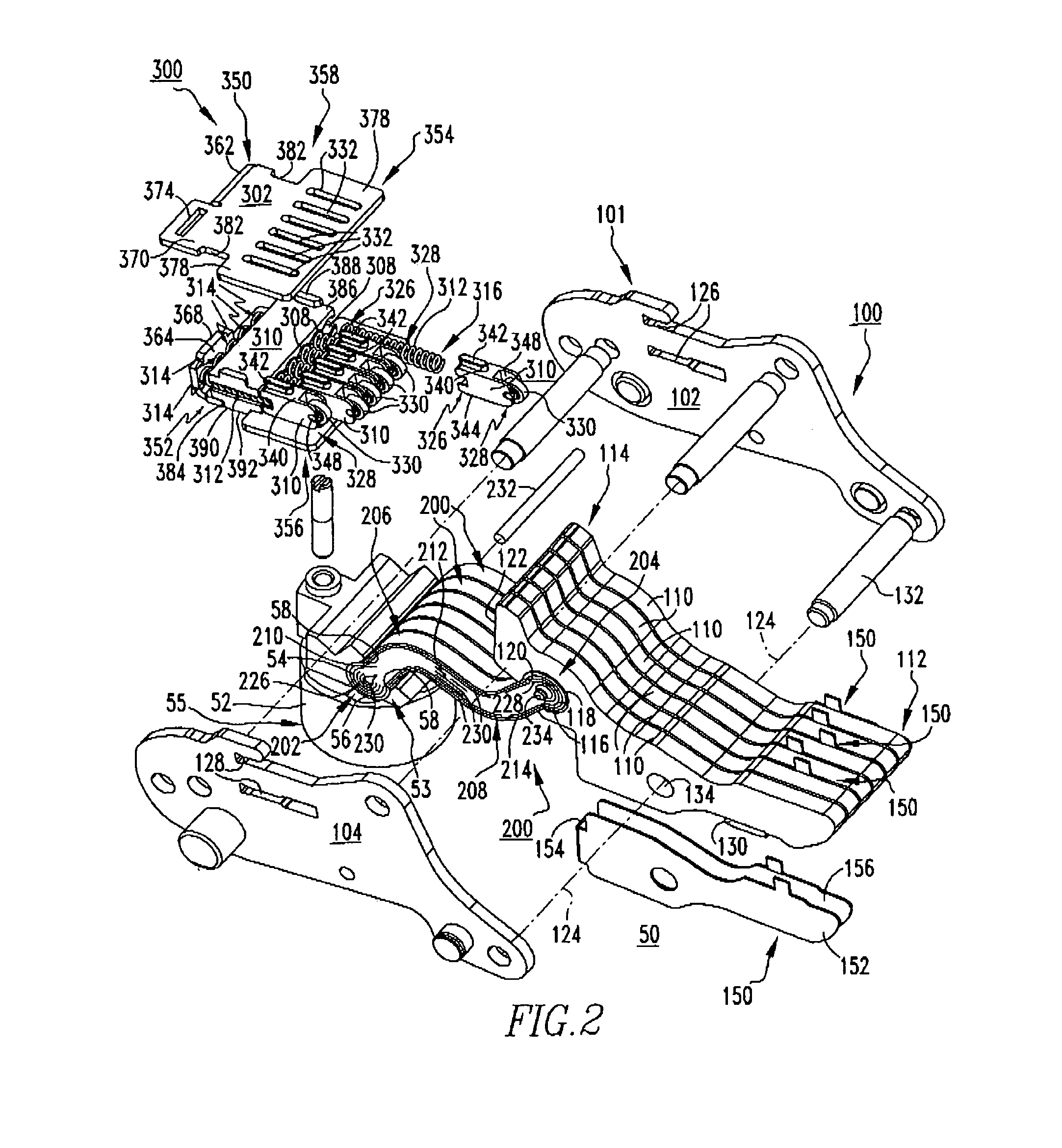
[0029]For purposes of illustration, embodiments of the invention will be described as applied to a contact spring assembly for the movable contact assembly of a low-voltage circuit breaker, although it will become apparent that they could also be applied to any known or suitable electrical switching apparatus (e.g., without limitation, circuit switching devices and circuit interrupters such as circuit breakers other than low-voltage circuit breakers, network protectors, contactors, motor starters, motor controllers and other load controllers).

[0030]Directional phrases used herein, such as, for example, left, right, clockwise, counterclockwise and derivatives thereof, relate to the orientation of the elements shown in the drawings and are not limiting upon the claims unless expressly recited therein.

[0031]As employed herein, the statement that two or more parts are “coupled” together shall mean that the parts are joined together either directly or joined through one or more intermedi...


PUM


Abstract

A contact spring assembly is provided for an electrical switching apparatus including a movable contact assembly and a stationary contact assembly having stationary electrical contacts. The movable contact assembly includes a carrier assembly, and movable contact arms pivotably coupled to the carrier assembly and carrying movable electrical contacts. The contact spring assembly includes a first contact spring housing member, a second contact spring housing member coupled to and disposed opposite from the first contact spring housing member, a spring guide disposed between and coupled to at least one of the first and second contact spring housing members and including spring holes, springs received in the spring holes, and sliders coupled to the springs. The springs and sliders individually bias the movable contact arms and movable electrical contacts toward engagement with corresponding stationary electrical contacts. A movable contact assembly and an electrical switching apparatus are also disclosed.

Description

CROSS-REFERENCE TO RELATED APPLICATIONS[0001]This application is related to commonly assigned, concurrently filed:[0002]U.S. patent application Ser. No. 11 / 549,316, filed Oct. 13, 2006, entitled “ELECTRICAL SWITCHING APPARATUS, AMD CARRIER ASSEMBLY AND INDEPENDENT PIVOT ASSEMBLY THEREFOR”;[0003]U.S. Pat. No. 7,351,927, issued Apr. 1, 2008 entitled “ELECTRICAL SWITCHING APPARATUS, AND CONDUCTOR ASSEMBLY, AND INDEPENDENT FLEXIBLE CONDUCTIVE ELEMENTS THEREFOR”; and[0004]U.S. patent application Ser. No. 11 / 549,294, filed Oct. 13, 2006, entitled “ELECTRICAL SWITCHING APPARATUS, AND HOUSING AND INTEGRAL POLE SHAFT BEARING ASSEMBLY THEREFOR”, all of which are hereby incorporated herein by reference.BACKGROUND OF THE INVENTION[0005](1)Field of the Invention[0006]The invention relates generally to electrical switching apparatus and, mare particularly, to electrical switching apparatus, such as circuit breakers, having contact spring assemblies.The invention also relates to contact spring ass...

Claims


Application Information

Patent Timeline
Patent Type & Authority Patents(United States)
IPC IPC(8): H01H75/00H01H77/00H01H83/00
CPCH01H1/226H01H1/24H01H1/50H01H1/5822
Inventor WEISTER, NATHAN J.POLLITT, WILLIAM C.SHEA, JOHN J.MARKS, DOUGLAS C.
Owner EATON INTELLIGENT POWER LTD
Why Eureka
Try Eureka