Reconfigurable lighted keypad

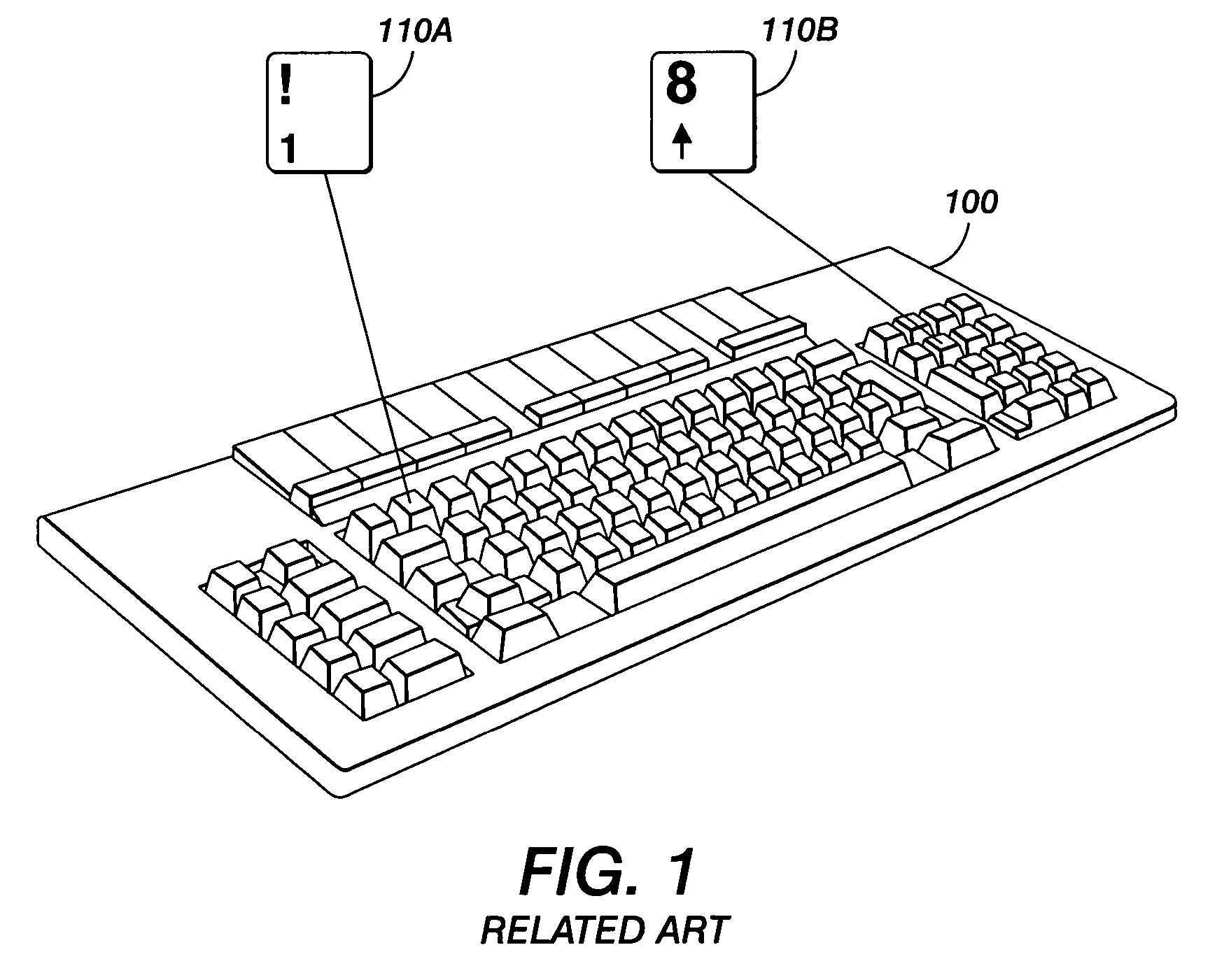
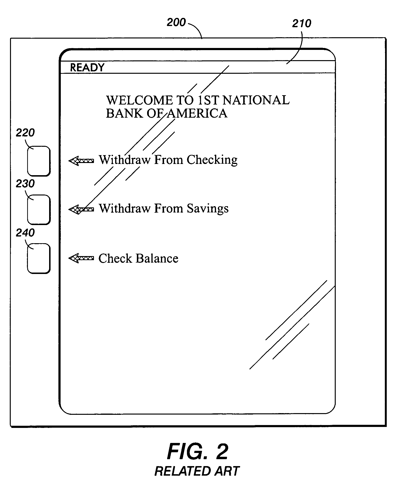
a keypad and lighted technology, applied in the field of rec, can solve the problems of severe drawbacks of static display presentation, insufficient static display when, and often the single label cannot describe all of the different contexts or modes of functionality of the button

Active Publication Date: 2009-01-13
XEROX CORP
View PDF23 Cites 12 Cited by
  • Summary
  • Abstract
  • Description
  • Claims
  • Application Information

AI Technical Summary

Benefits of technology

[0016]In various exemplary embodiments, the dynamically reconfigurable display and input button may be provided in a user interface of a consumer electronics device.
[0017]In various other exemplary embodiments of the systems and methods of the invention, the dynamically reconfigurable display and input button may be provided on a user interface for office equipment.
[0018]Various aspects of the invention are achieved by a user interface for a device having an integrated input button and input function display. The interface includes at least one physically displaceable input button (e.g., mechanical button) and a dynamically reconfigurable display operatively provided on the at least one input button. The input button is operatively coupled to a device controller to actuate at least one device function through displacement of the at least one displaceable input button by a user of the device. The display is operatively provided on the at least one input button and externally viewable by the user. The display is dynamically reconfigured to display indicia indicating input button functionality.

Problems solved by technology

However, a single label often will not suffice to describe all of the different contexts or modes of functionality of the button in order to inform a user as to the capability and functionality of the individual buttons.
However, such static display presentation has severe drawbacks, particularly if more than two function are necessary, as in the third example.
Static display also does not suffice when a dynamic reconfiguration of button functionality is desired.
One such drawback is the inability to further reconfigure the button without a corresponding substitution of a button component, e.g., a keyboard button having the correct new functionality printed on its operating face to enable the user to properly use the new function.
Also, when more than two functions are provided, printing of all functions on the button is either impractical or at least undesirably confusing to a user.
These alternatives create their own problems, by requiring either learned knowledge or memorization of the new (or old) functionality by a user, or viewing of a remote listing or display of all of a plurality of features for a particular button.
None of these latter options are highly user friendly or readily adaptable to a dynamically changing button operation.
Moreover, such alternatives are difficult to operate due to the functionality being displayed remotely from the button itself.
However, touch screens also are prone to many problems.
They are subject to wear and tear.
Touch screens further do not lend themselves to rapid, repetitive keystrokes.
This reduces productivity.
Moreover, it is often mentally taxing to operate a touch screen.
Thus, it is often difficult to assess whether a touch screen button has been properly depressed without looking for or hearing other perceptible clues, such as a display change or audible queue.
Accordingly, touch screens are more difficult to assess than the tactile sensation of depressing a physically displaceable button.
Additionally, touch screens often take up much needed display space, reducing the overall functionality of the display itself.

Method used


Image

  • Reconfigurable lighted keypad
  • Reconfigurable lighted keypad
  • Reconfigurable lighted keypad

Examples


Embodiment Construction

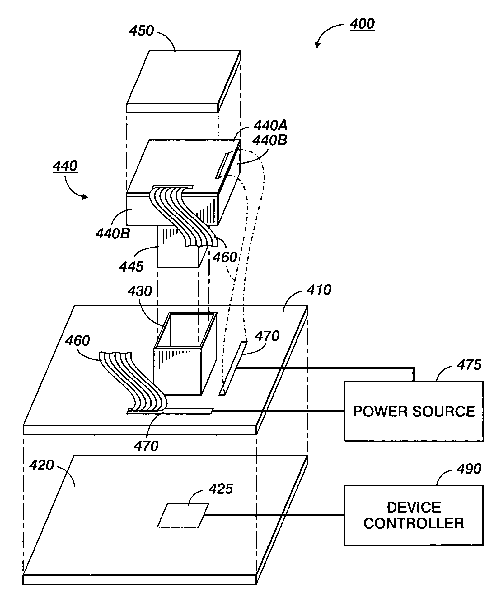
[0030]A first embodiment of the invention will be described with reference to FIGS. 4-7, which show an exemplary reconfigurable keypad 400 having at least one physically displaceable button 440 and an integrated dynamically reconfigurable display 450. The button is used as an input mechanism for an electronic device in which one or more of such buttons are provided. The keypad 400 includes, as mentioned, at least one physically-displaceable button 440 and a dynamically reconfigurable display 450 that is operatively provided on a surface of the button 440, such as on an operational face 440A that receives an actuating force to depress the button. Alternatively, the display may be embedded within the button 440 and visible from at least one surface of button 440. If the operational face is transparent or translucent, the display may be provided internally within the button, so long as it is viewable externally by a user of the user interface.

[0031]The keypad button 440 can take many c...


PUM


Abstract

A dynamically reconfigurable input button display provided on an operational face of multi-function physically displaceable buttons allows easy dynamic display of various operating modes or functions associated with operation of the button. The button forms part of a user interface of a input device, such as a piece of office equipment or a hand-held electronics device. The buttons may form an array in which a plurality of discrete functionality displays are provided on each of the buttons. The display is a thin film device, such as an organic LED display.

Description

BACKGROUND OF THE INVENTION[0001]1. Field of Invention[0002]A dynamically reconfigurable button display provided on an operational face of multi-function physically displaceable buttons allows easy dynamic display of various operating modes or functions associated with operation of the button.[0003]2. Description of Related Art[0004]Reconfigurable controls are known per se. For example, conventional computer keyboards and keypads, such as those illustrated in FIG. 1, are capable of performing multiple operations (e.g., a computer keypad button is able to operate as either a numeric keypad or as a cursor control, depending on a mode of operation). However, a single label often will not suffice to describe all of the different contexts or modes of functionality of the button in order to inform a user as to the capability and functionality of the individual buttons.[0005]One specific example is the “8” key (element 110B) on a standard keyboard keypad 100. It is usually associated with ...

Claims


Application Information

Patent Timeline
Patent Type & Authority Patents(United States)
IPC IPC(8): G06F3/02G09G5/00
CPCG06F3/0238
Inventor RAY, ELTON T.
Owner XEROX CORP
Why Eureka
Try Eureka