LED surface-mount device and LED display incorporating such device

a surface-mount device and led display technology, applied in the field of electronic packaging, can solve the problems of increasing the viewing angle, discharging heat enough to require thermal management, and affecting the color fidelity of surface-mount devices and many other types of electronic packages, so as to achieve the effect of improving color fidelity

Inactive Publication Date: 2009-03-19
CREE HUIZHOU SOLID STATE LIGHTING
View PDF110 Cites 83 Cited by
  • Summary
  • Abstract
  • Description
  • Claims
  • Application Information

AI Technical Summary

Benefits of technology

[0011]In accordance with yet another specific, exemplary embodiment, there is provided an LED display comprising a substrate carrying an array of surface-mount devices arranged in vertical columns and horizontal rows, each of the SMDs containing a vertically oriented, linear arrangement of three LEDs adapted to be energized to produce in combination a substantially fill range of colors and to define one pixel of the display. Signal processing and LED drive circuitry is electrically connected to selectively energize the array of SMDs for producing visual images on the display. The linear orientation of the LEDs has been found to improve color fidelity over a wide range of viewing angles.

Problems solved by technology

Although these displays are viewable across a substantial range of off-axis angles, for example, up to 145° or even greater, there is often a perceptible loss of color fidelity with increasing viewing angle.
It is well-known that surface-mount devices and many other types of electronic packages, whether containing integrated circuits or discrete components such as diodes or power transistors, dissipate sufficient heat to require thermal management.
However, the leads often do not have sufficient mass or exposed surface area to provide effective heat dissipation.
For example, high intensity light emitting diodes (LEDs) that emit light principally in the visible part of the electromagnetic spectrum can generate significant amounts of heat that is difficult to dissipate using such conventional techniques.

Method used


Image

  • LED surface-mount device and LED display incorporating such device
  • LED surface-mount device and LED display incorporating such device
  • LED surface-mount device and LED display incorporating such device

Examples


Embodiment Construction

[0025]The following description presents preferred embodiments of the invention representing the best mode contemplated for practicing the invention. This description is not to be taken in a limiting sense but is made merely for the purpose of describing the general principles of the invention whose scope is defined by the appended claims.

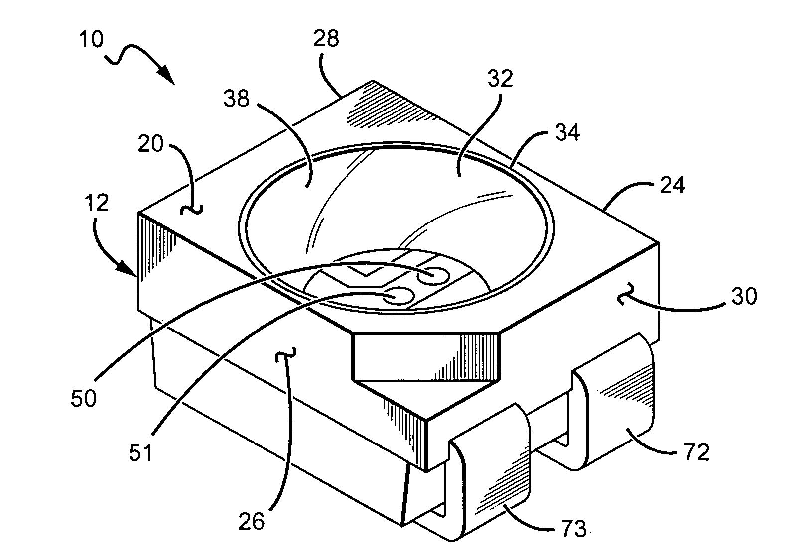
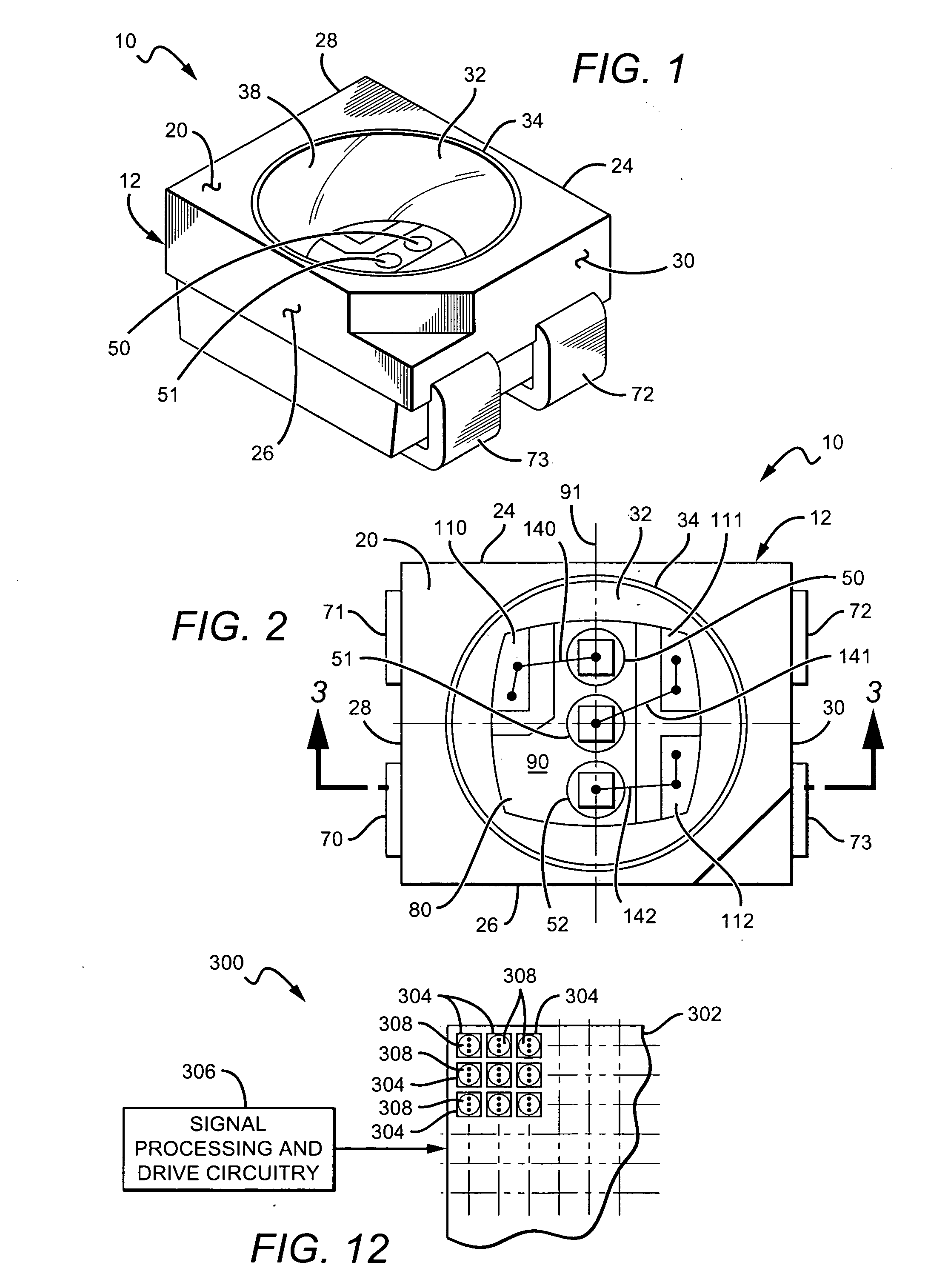
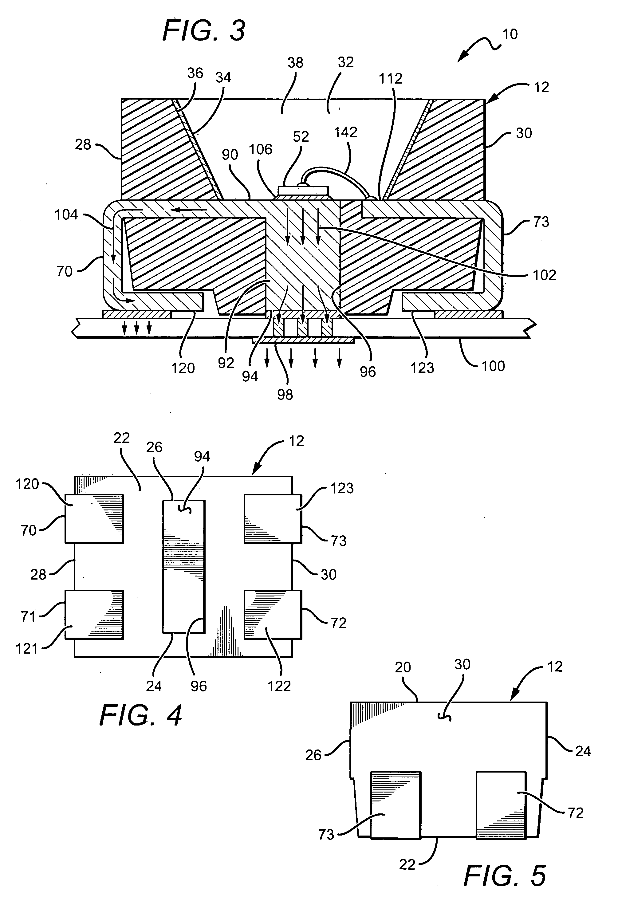
[0026]FIGS. 1-8 depict a surface-mount device (SMD) 10 and parts thereof according to specific, exemplary embodiments for use in LED displays such as indoor LED screens. The SMD 10 includes a casing 12 carrying a lead frame 14 comprising a plurality of electrically conductive connection parts, in this example four parts 16-19.

[0027]The casing 12 may be generally in the form of a rectangular prism, comprising opposed, parallel upper and lower surfaces 20 and 22, respectively, side surfaces 24 and 26 and end surfaces 28 and 30.

[0028]By way of example and not limitation, the SMD 10 may have an overall length of 3.20 mm, an overall width of 2.80 mm, an...


PUM


Abstract

In one embodiment, a surface-mount device comprises a casing having opposed, first and second main surfaces, side surfaces, and end surfaces. A lead frame partially encased by the casing comprises (1) an electrically conductive LED chip carrier part having a surface carrying a linear array of three LEDs adapted to be energized to produce in combination a substantially full range of colors, each LED having a first electrical terminal and a second electrical terminal, the first terminal of each of the three LEDs being electrically and thermally coupled to the chip carrying surface of the chip carrier part; and (2) three electrically conductive connection parts separate from the chip carrier part, each of the three connection parts having a connection pad, the second terminal of each of the three LEDs being electrically coupled to the connection pad of a corresponding one of the three connection parts with a single wire bond. The linear array of LEDs extends in a first direction, and each of the chip carrier part and three connection parts has a lead. The leads are disposed in parallel relationship with each other and extend through the end surfaces of the casing in a second direction, the second direction being orthogonal to the first direction. An array of the surface-mount devices may be used in an LED display such as an indoor LED screen.

Description

FIELD OF THE INVENTION[0001]The present invention relates generally to electronic packaging, and more particularly to surface-mount devices for use in LED displays.BACKGROUND[0002]With the advent of LEDs of increased brightness and color fidelity together with improved image processing technology, large format, full color LED video screens became available and are now in common use. Large format LED displays typically comprise a combination of individual LED panels providing image resolutions determined by the distance between adjacent pixels or “pixel pitch”. Outdoor displays that are intended for viewing from greater distances have relatively large pixel pitches and usually comprise discrete LED arrays in which a cluster of individually mounted red, green and blue LEDs are driven to form what appears to the viewer to be a full color pixel. Indoor screens, on the other hand, requiring shorter pixel pitches, for example, as small as 3 mm or less, typically comprise panels carrying r...

Claims


Application Information

Patent Timeline
Patent Type & Authority Applications(United States)
IPC IPC(8): H01L33/00H01L33/64
CPCH01L25/0753H01L33/642H01L33/647H01L2924/09701H01L2224/32245H01L2224/48247H01L2224/73265H01L2924/00H01L2224/48091H01L2224/4809H01L2924/00014
Inventor CHAN, ALEX CHI KEUNGWANG, XUAN
Owner CREE HUIZHOU SOLID STATE LIGHTING
Why Eureka
Try Eureka