

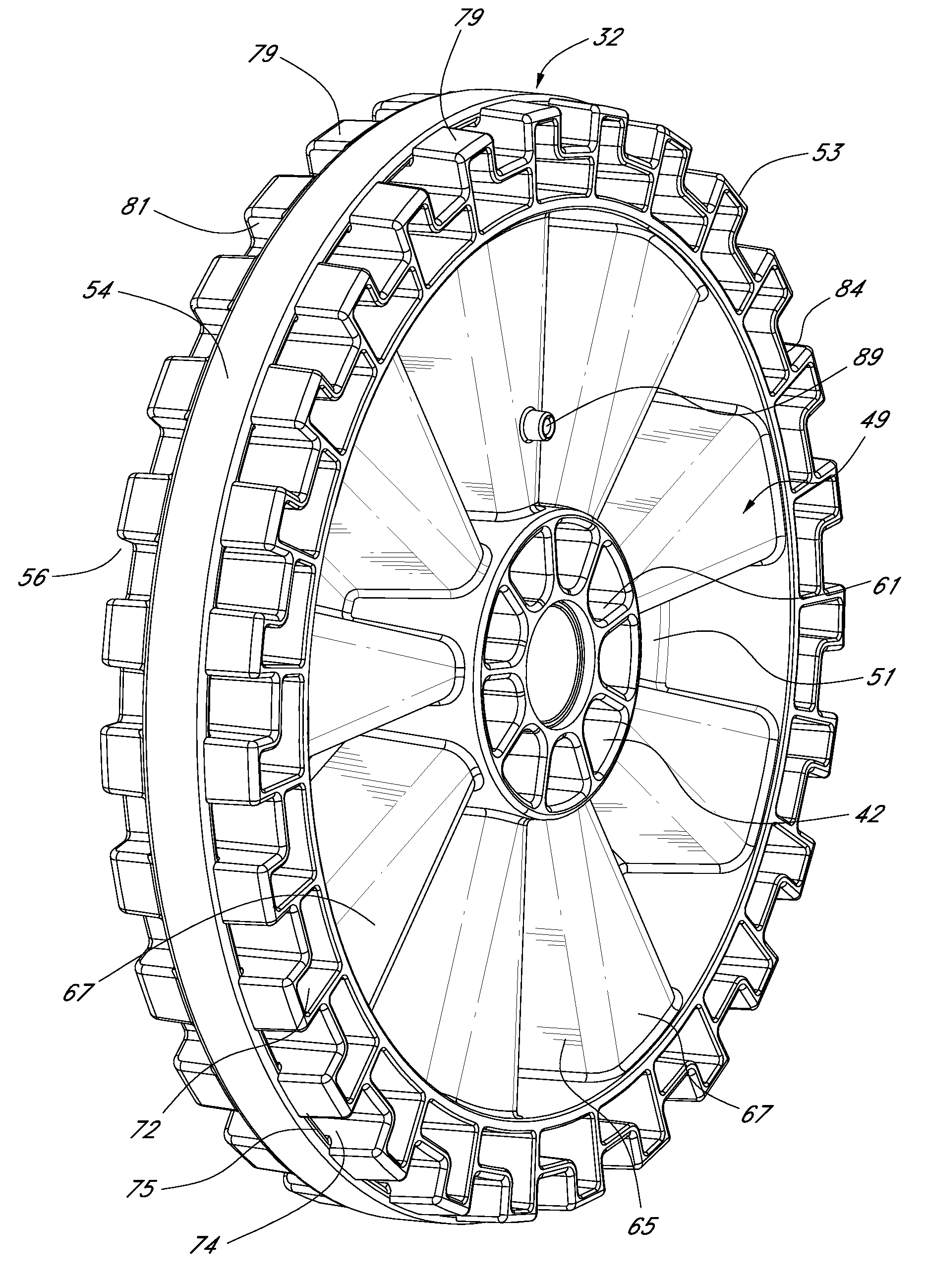
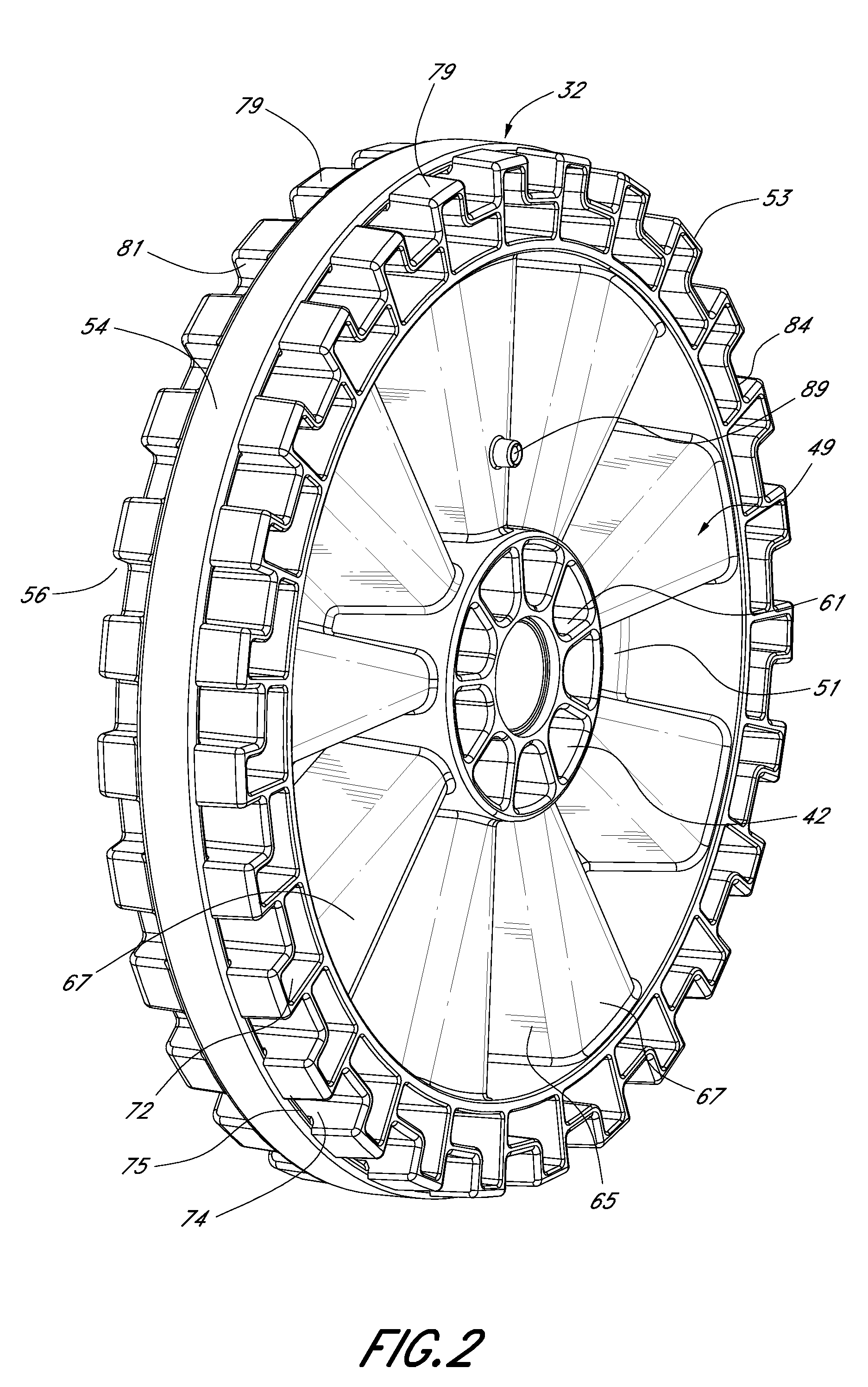
Injection-molded wheel having a plurality of recesses in a rim portion
a technology of injection molding and rim portion, which is applied in the field of wheels, can solve the problems of lack of superior strength, high cost, and high manufacturing process cost, and thus the wheel may be subject to strong forces and exposed to harsh environments
- Summary
- Abstract
- Description
- Claims
- Application Information
AI Technical Summary
Benefits of technology
Problems solved by technology
Method used
Image

Examples
Embodiment Construction
[0034]Reference will now be made in detail to the preferred embodiments of the invention, examples of which are illustrated in the accompanying drawings. While the invention will be described in conjunction with the preferred embodiments, it will be understood that they are not intended to limit the invention to those embodiments. On the contrary, the invention is intended to cover alternatives, modifications and equivalents, which may be included within the spirit and scope of the invention as defined by the appended claims.
[0035]For convenience in explanation and accurate definition in the appended claims and detailed description, the terms “up” or “upper”, “down” or “lower”, “inside” and “outside” are used to describe features of the present invention with reference to the positions of such features as displayed in the figures.
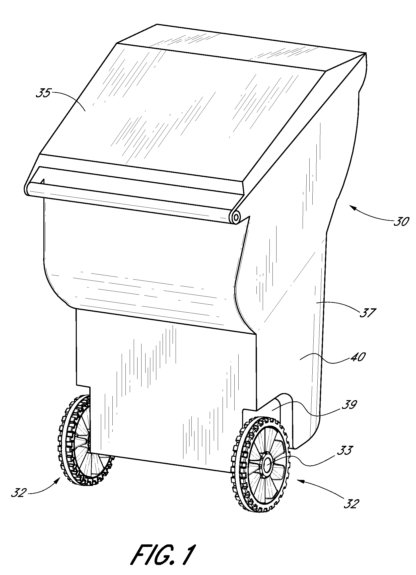
[0036]The wheel and method of molding a wheel of the present invention can be used in connection with numerous wheeled devices including refuse carts, whee...
PUM
 Abstract
Description
Claims
Application Information