Rotor with cut-outs

a technology of rotors and cutting holes, which is applied in the direction of machines/engines, rotary/oscillating piston pump components, liquid fuel engines, etc., can solve the problems of rough operation of the associated piece of equipment and the tendency of the motor to run roughly

Inactive Publication Date: 2009-01-27
WHITE DRIVE PROD INC
View PDF13 Cites 14 Cited by
  • Summary
  • Abstract
  • Description
  • Claims
  • Application Information

AI Technical Summary

Problems solved by technology

When the motor, especially a hydraulic motor of the spool valve type, is operated at a low speed and a high torque, if there was a substantial amount of leakage, the motor tends to run roughly.
Such inconsistency can result in rough operation of the associated piece of equipment driven by the gerotor motor.

Method used


Image

  • Rotor with cut-outs
  • Rotor with cut-outs
  • Rotor with cut-outs

Examples


Embodiment Construction

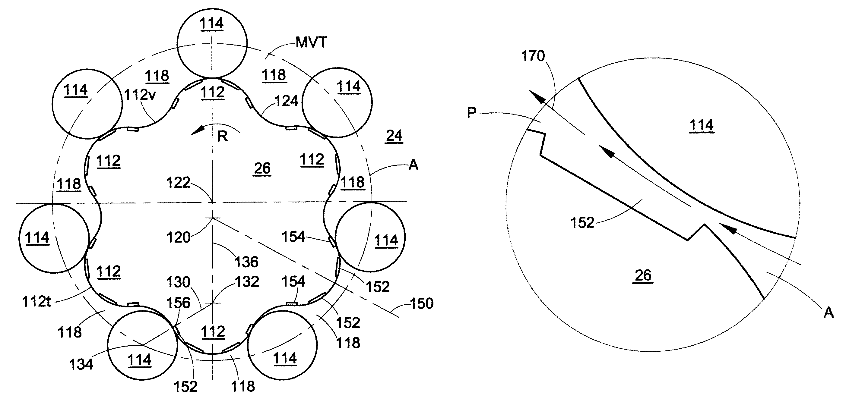
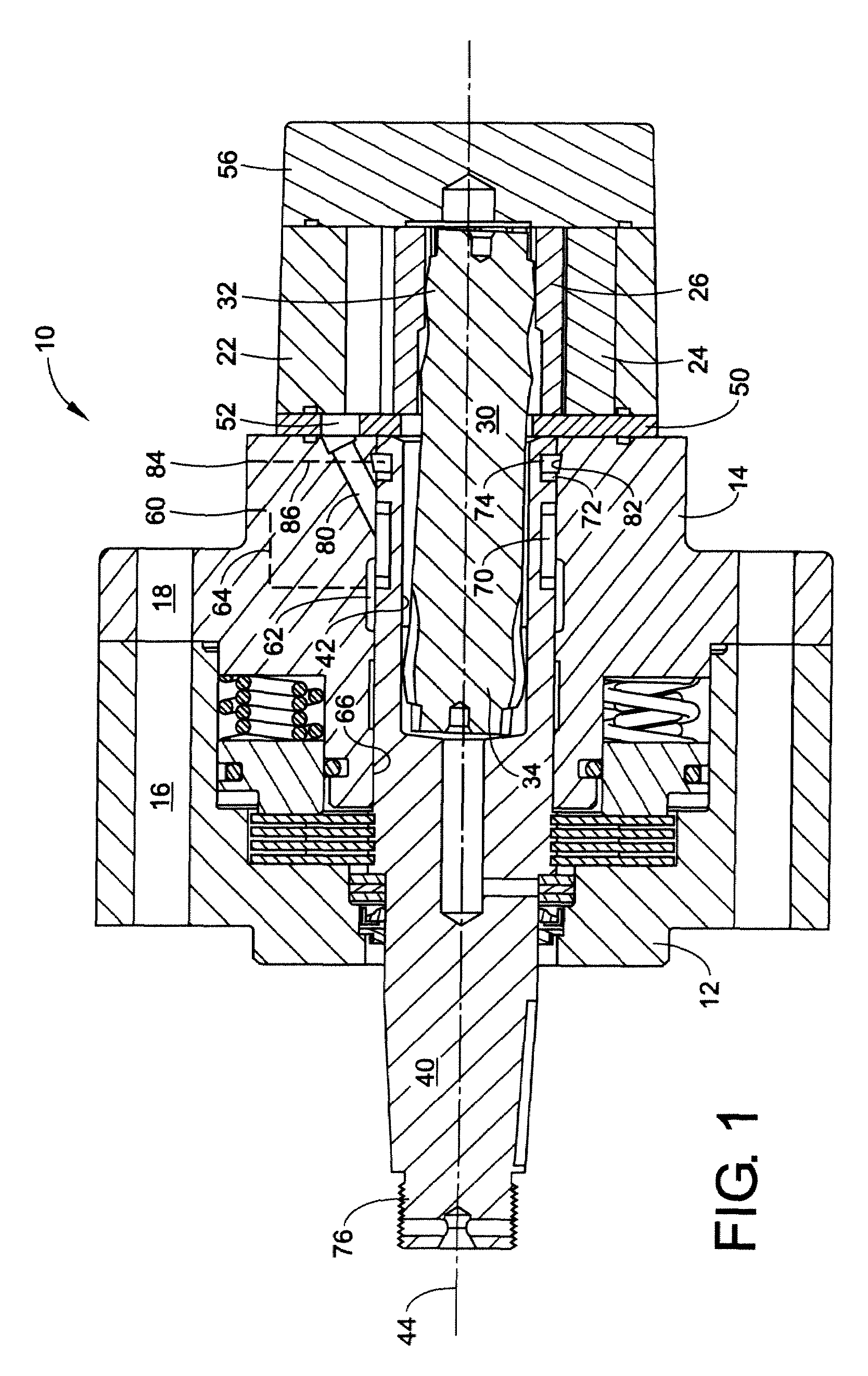
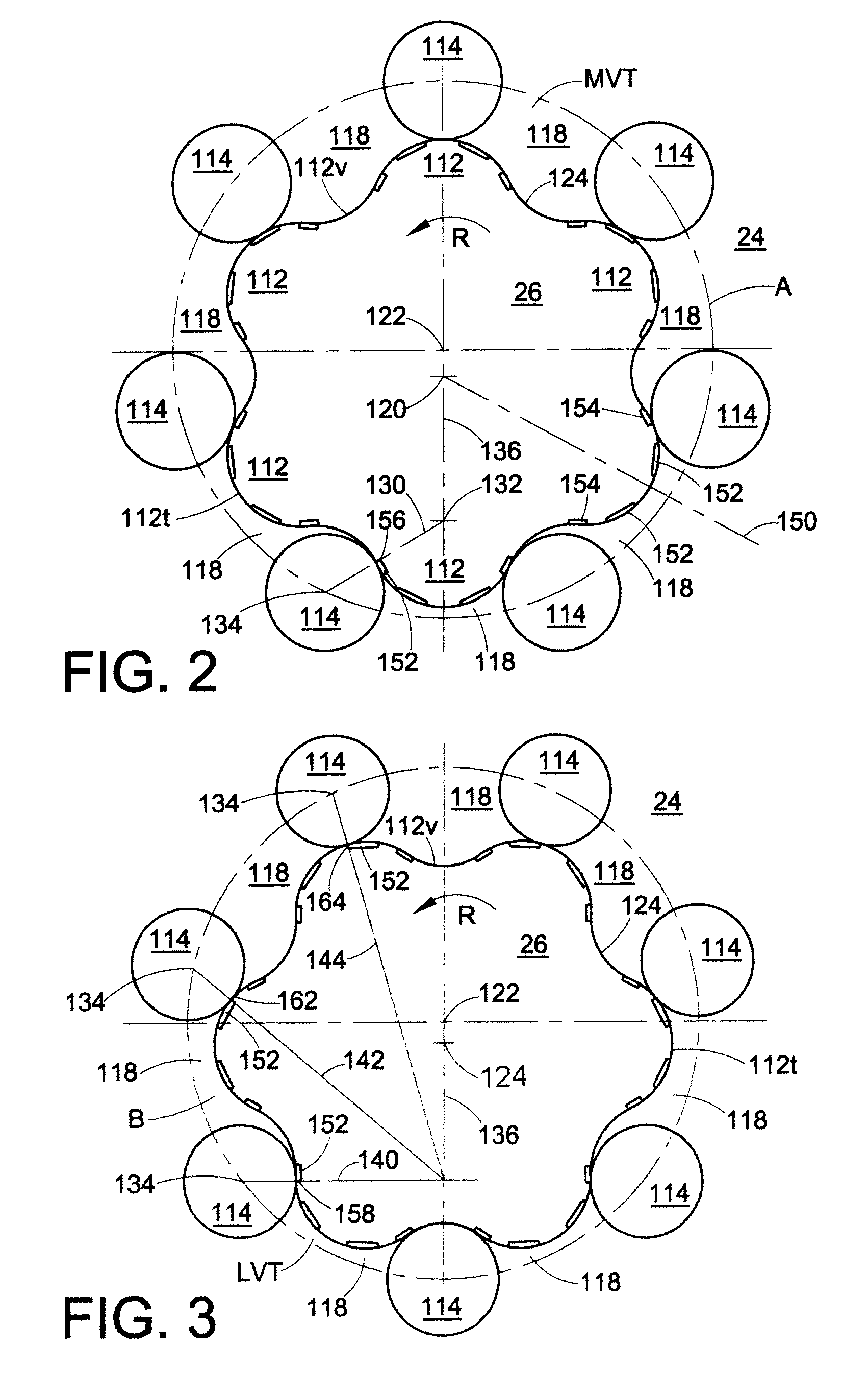
[0015]With reference to FIG. 1, a hydraulic gerotor device 10 includes a housing assembly that includes a front housing section 12 and a rear housing section 14. The housing sections attach to one another via bolts (not shown) received in bolt holes 16 and 18 formed in the housing sections. A rotor assembly 22 connects to the rear housing section 14. In the depicted embodiment, the rotor assembly 22 includes a stator 24 and a rotor 26, which will be described in more detail below. A wobble stick 30, also referred to as a drive link or a wobble shaft, connects to the rotor 26 at a first end 32. The wobble stick 30 can attach to the rotor 26 via a splined connection, which is known in the art. The first end 32 of the wobble stick 30 rotates and orbits relative to the stator 24 as the rotor 26 rotates and orbits relative to the stator. A second end 34 of the wobble shaft 30 connects to an output shaft 40. The output shaft 40 includes a central opening 42 aligned along its rotational ax...


PUM


Abstract

A gerotor device having a rotor and a stator, the rotor including a plurality of teeth defining a profile, each tooth being divided by a tooth axis. At least one tooth includes an inner recess and an outer recess spaced from the inner recess along the profile.

Description

BACKGROUND[0001]Hydraulic devices are excellent for transferring large amounts of torque into remote locations. The torque is generated by capturing a pressurized fluid within an expanding gerotor cell. The gerotor cells are defined by the contact between the teeth of a rotor and the lobes of a surrounding stator. This contact divides the pressure arc between the rotor and the stator into a series of gerotor cells.[0002]Among the performance characteristics that are considered important in low-speed, high-torque gerotor motors are volumetric efficiency and smooth operation. When the motor, especially a hydraulic motor of the spool valve type, is operated at a low speed and a high torque, if there was a substantial amount of leakage, the motor tends to run roughly. Such inconsistency can result in rough operation of the associated piece of equipment driven by the gerotor motor.BRIEF DESCRIPTION[0003]An example of a hydraulic device that overcomes the aforementioned shortcomings inclu...

Claims


Application Information

Patent Timeline
Patent Type & Authority Patents(United States)
IPC IPC(8): F01C1/10
CPCF03C2/08F04C2/084F04C2/088F04C2/103
Inventor WHITE, JR., HOLLIS N.
Owner WHITE DRIVE PROD INC
Why Eureka
Try Eureka