Head-up display

a display and head-up technology, applied in the field of displays, can solve the problems of generating significant heat, consuming more power than the crt source, and comparatively fragile crt sources, and achieve the effect of facilitating the s-polarization orientation

Active Publication Date: 2009-01-27
HONEYWELL INT INC
View PDF11 Cites 86 Cited by
  • Summary
  • Abstract
  • Description
  • Claims
  • Application Information

AI Technical Summary

Problems solved by technology

While current head-up displays are very useful may suffer from a number of disadvantages well known in the art.
CRT sources are comparatively fragile, may consume more power than is desired, may generate significant heat, and may be undesirably bulky.
Attempts to employ flat panel liquid crystal displays (LCDs) have not yet achieved widespread success, in part because of the difficulty of providing sufficient luminance for the superimposed information.

Method used


Image

  • Head-up display
  • Head-up display
  • Head-up display

Examples


Embodiment Construction

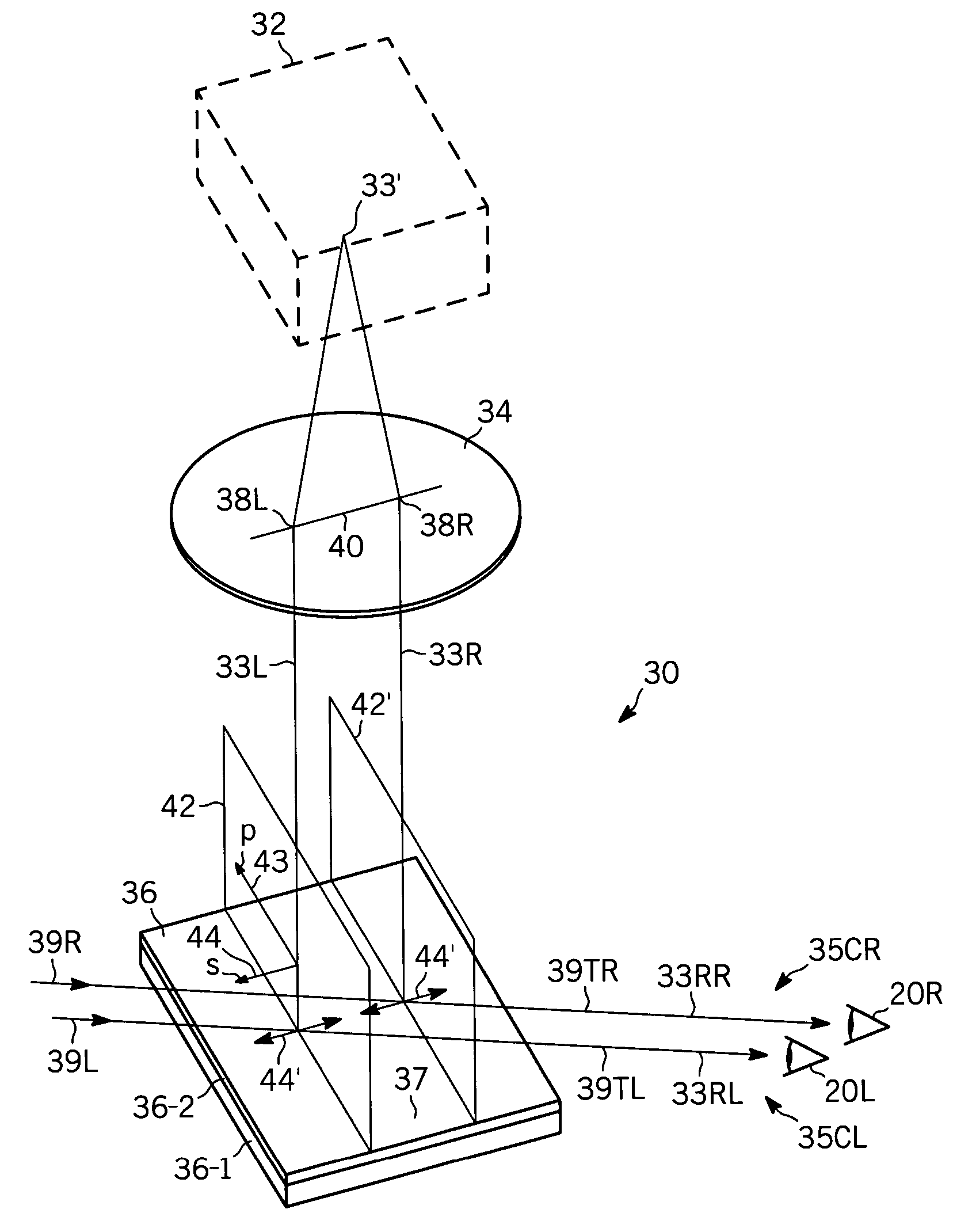
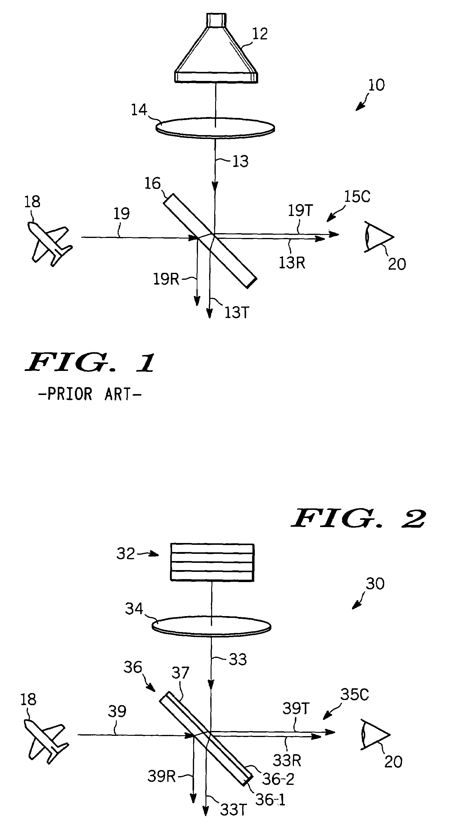
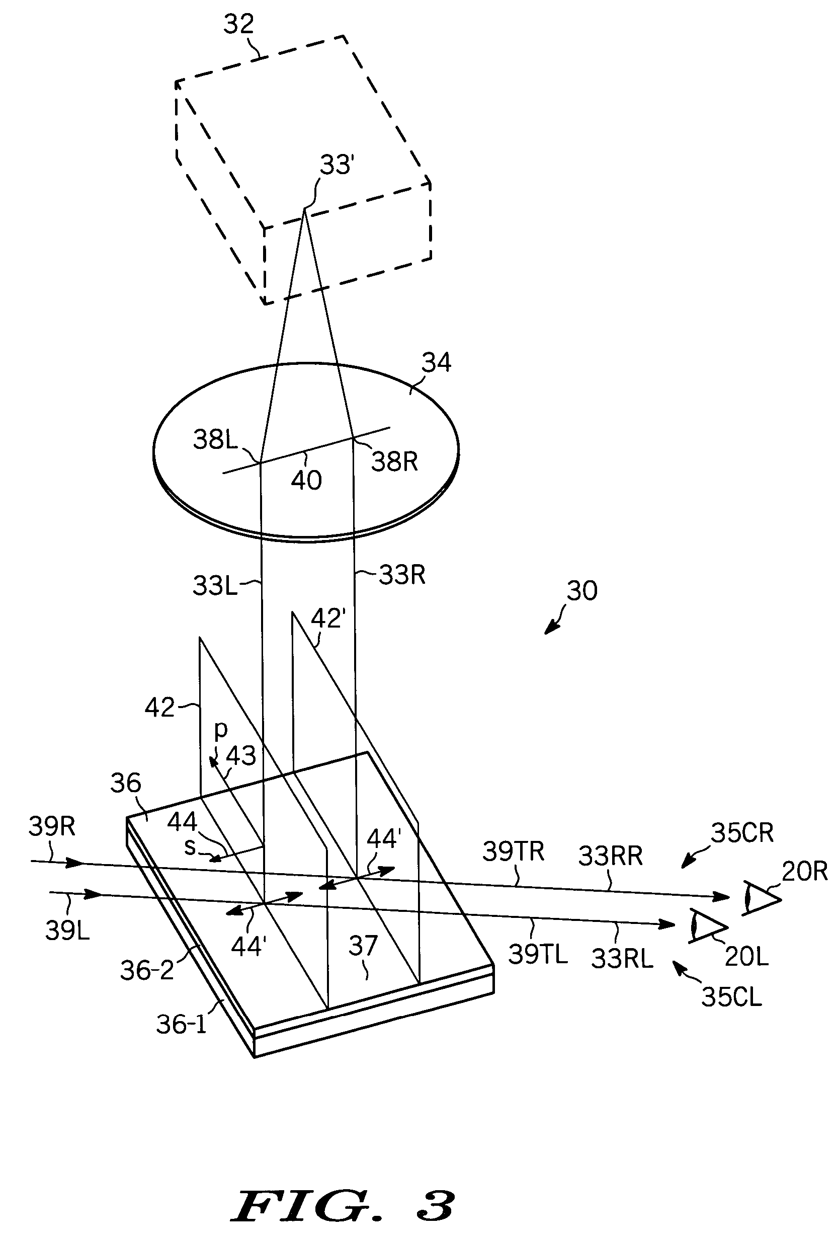
[0013]The following detailed description is merely exemplary in nature and is not intended to limit the invention or the application and uses of the invention. Furthermore, there is no intention to be bound by any expressed or implied theory presented in the preceding technical field, background, brief summary or the following detailed description. For convenience of description the words “background scene” are used to refer to the (e.g., far field) scene that a viewer sees looking through the combiner of a head-up display. The word “data” is used to refer to whatever graphics, text, numbers, letters or other images are being generated by the data source of the head-up display and superimposed on the background scene and the word “combiner” is used to refer to the semi-transparent, semi-reflecting optical plate in the field of view of the user that combines the background scene and data images so that they appear to the viewer to be superimposed. Such terminology is conventional.

[00...


PUM


Abstract

Methods and apparatus are provided for a combined image on a head-up display. A data image display provides a first part of a combined image. An optical input provides a second part of the combined image, e.g., the background scene. A combiner superimposes the first and second parts to provide the combined image to the viewer. The data image display preferentially delivers s-polarized light to the combiner, which has a selective reflectance region for preferentially reflecting s-polarized light in a wavelength region of interest. In a preferred embodiment, the data image display comprises a backlight, a liquid crystal layer and two polarizers oriented so that the data images directed toward the combiner are s-polarized with respect to the selective reflectance region. A polarization rotation element may also be used in the data image display to facilitate s-polarization orientation.

Description

TECHNICAL FIELD[0001]The present invention generally relates to displays, and more particularly relates to head-up displays.BACKGROUND[0002]It is known in the art to provide users with a transparent viewing screen through which they are able to see, for example, approaching terrain, objects or other far-field or background scene, on which is superimposed various messages, instrument readings or other data. The superimposed information is transparent and appears to float in space in front of the far-field or background scene being viewed through the display. This type of display is commonly referred to as a “head-up display” since the user is able to see the superimposed information without having to look away from the far field or background scene or object.[0003]While current head-up displays are very useful may suffer from a number of disadvantages well known in the art. For example, current head-up displays usually employ cathode ray tube (CRT) image sources for the superimposed ...

Claims


Application Information

Patent Timeline
Patent Type & Authority Patents(United States)
IPC IPC(8): G09G5/00
CPCG02B27/0101G02B5/30G02B2027/0118
Inventor LARSON, BRENT DDUBIN, MATTHEW B.HAIM, ELIAS S.
Owner HONEYWELL INT INC
Why Eureka
Try Eureka