
Bicycle lighting apparatus with mountable display

a technology of lighting apparatus and bicycle, which is applied in the field of bicycles, can solve the problems of cumbersome operation, crowded and cluttered handlebars, and difficulty in mounting both the display and the headlight in the central portion of the handlebars

Inactive Publication Date: 2009-02-17
SHIMANO INC
View PDF36 Cites 8 Cited by
  • Summary
  • Abstract
  • Description
  • Claims
  • Application Information

AI Technical Summary

Benefits of technology

The present invention is about a device that can hold a light and a display on a bike. The device has a part that can hold a separate display and is attached to a lighting case. This makes it easy to mount a light and a display on a bike. The invention has various features that make it easier to use and more convenient for riders.

Problems solved by technology

Unfortunately, it is difficult to mount both the display and the headlight in the central portion of the handlebar because of the limited space available at that location.
While the above method allows a display and a headlight to be mounted together on the handlebar, the display and the headlight must be separately mounted to the device mounting parts, which can be a cumbersome operation.
Also, because the entire structure comprises a number of individual components mounted together, the handlebar tends to have a crowded and cluttered appearance.
Also, since the display faces rearwardly, the rider must look down at a significant angle in order to view the display, which can be uncomfortable.

Method used


Image

  • Bicycle lighting apparatus with mountable display
  • Bicycle lighting apparatus with mountable display
  • Bicycle lighting apparatus with mountable display

Examples


case 40

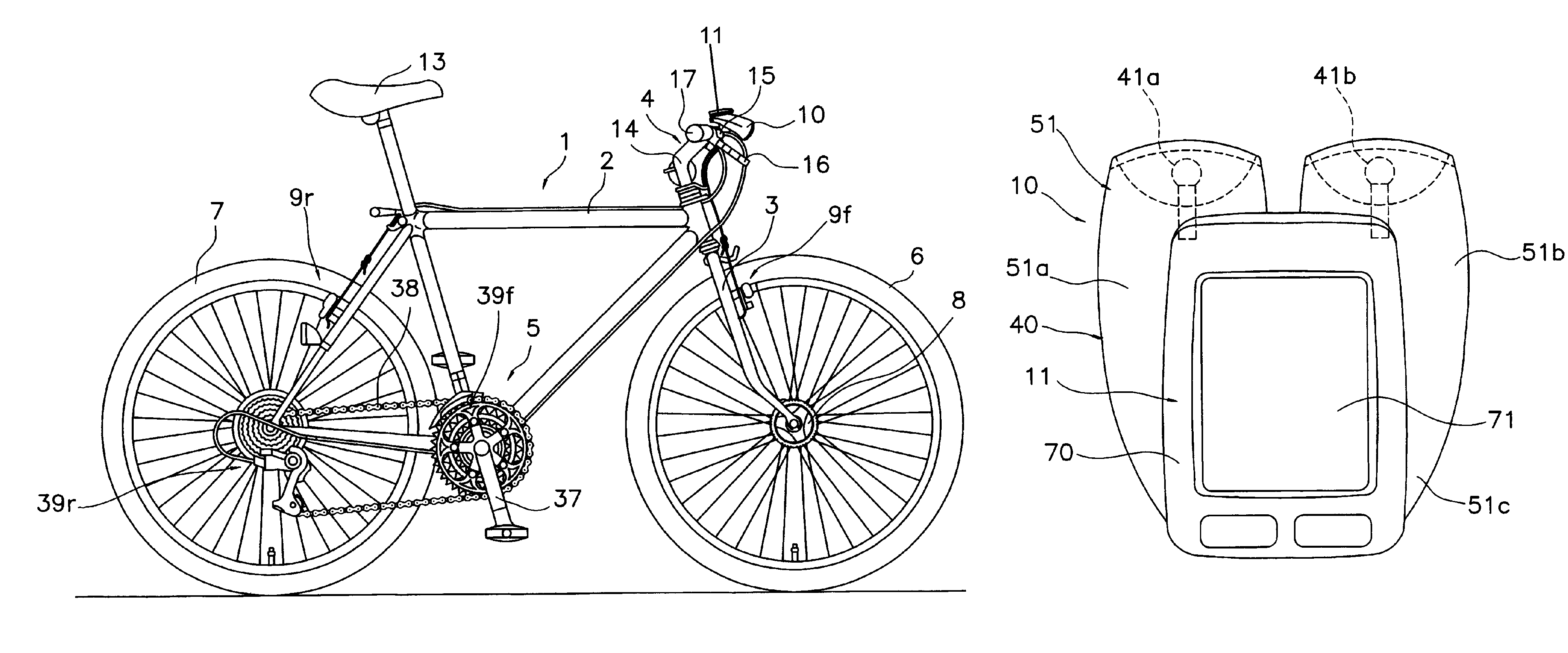
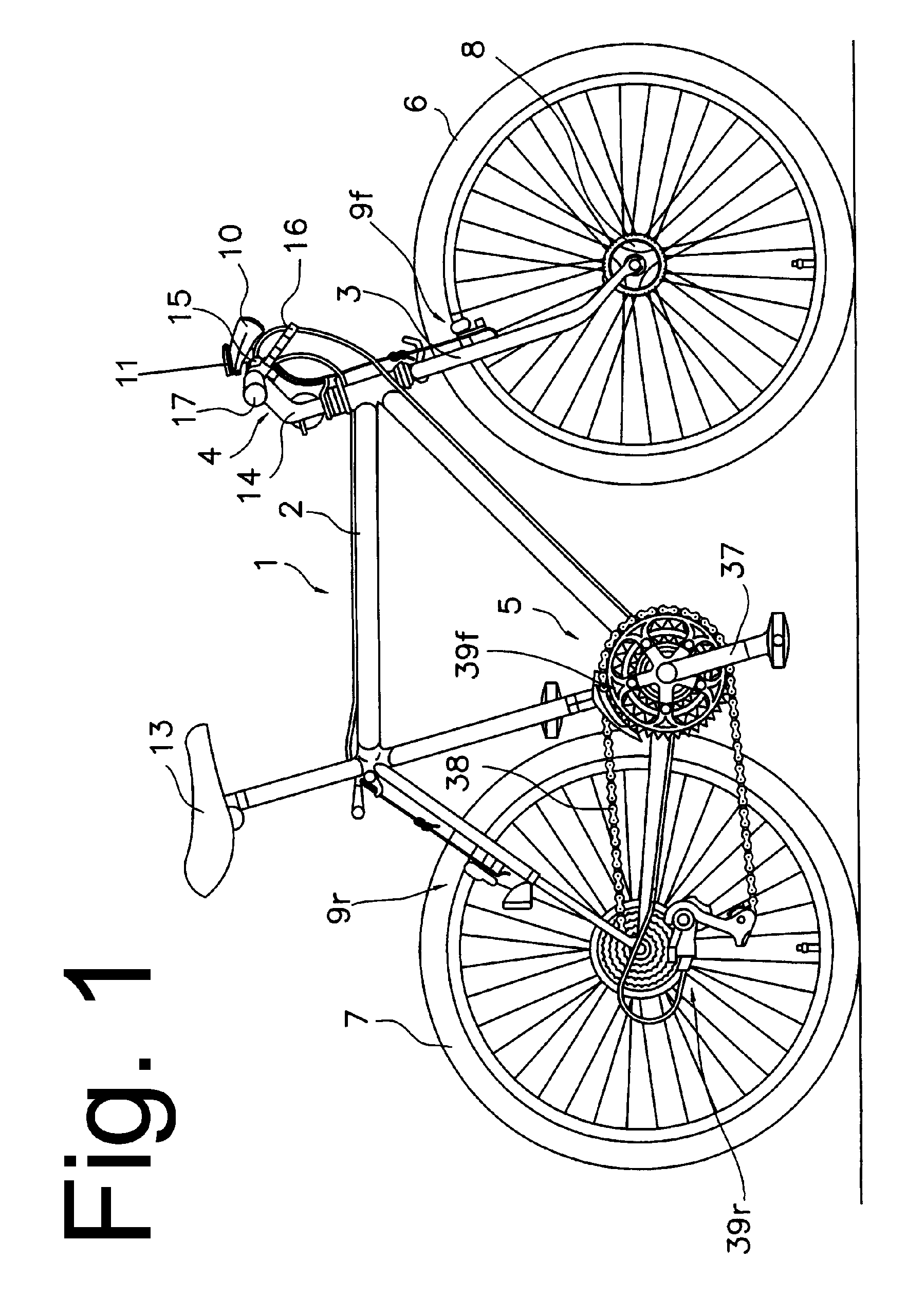
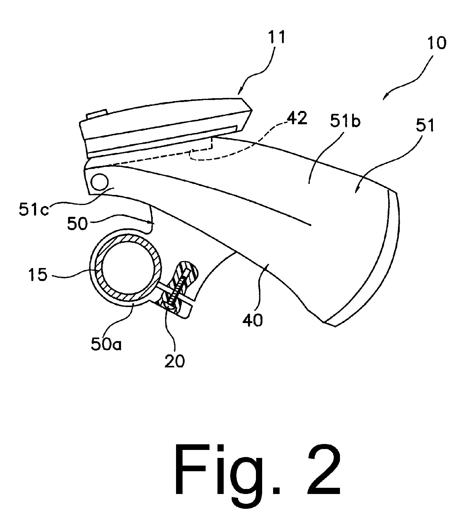
[0018]Lighting case 40 comprises a bracket 50 and a case body 51. Bracket 50 includes a pair of circular clamps 50a structured to be mounted to handlebar 15 on opposite sides of stem 14 through screws 20 in a conventional manner. Case body 51 comprises a pair of branched tubular lighting element housings 51a and 51b and a controller housing 51c. Lighting case mounting unit 42 is formed in a generally rectangular recessed area on the upper surface of controller housing 51c. Lighting elements 41a and 41b are housed within lighting element housings 51a and 51b, and a lighting control unit 45 (FIG. 7) is housed within controller housing 51c. In this embodiment, lighting element 41a comprises a xenon bulb, and lighting element 41b comprises a plurality of white LED's. In this manner, lighting element 41a illuminates distant objects with a narrow angle of illumination, whereas lighting element 41b illuminates objects near the front of the bicycle with a wide angle of illumination.

[0019]As...


PUM


Abstract

A bicycle lighting apparatus comprises a lighting case structured to be mounted to the bicycle and a lighting element supported by the lighting case. A lighting case mounting unit is disposed on the lighting case and is structured to detachably mount a separate display unit to the lighting case.

Description

BACKGROUND OF THE INVENTION[0001]The present invention is directed to bicycles and, more particularly, to a bicycle lighting apparatus that can mount a separate display.[0002]Various components are mounted to bicycle handlebars in order to control the operation of the bicycle. Such components include brake levers, transmission control devices such as derailleur operating levers, and headlights for illuminating the road at night. Cycle computers and / or gear indicators also may be mounted to the handlebar in order to electronically control the bicycle transmission and / or to display operating and other information to the rider. A typical cycle computer and / or gear indicator usually comprises a bracket, wherein the bracket is adapted to be mounted to the bicycle handlebar, and a display that is detachably mounted to the bracket.[0003]It is preferable that both the indicator and the headlight be mounted onto the central portion of the handlebar. By so doing, the rider may view the displa...

Claims


Application Information

Patent Timeline
Patent Type & Authority Patents(United States)
IPC IPC(8): B62J6/00B60Q1/00F21V33/00F21V7/04H04M1/22B62J6/02B62J11/00B62J99/00
CPCB62J6/02B62J99/00B62J11/00B62J2099/0026B62J50/22B62J6/03B62J50/225
Inventor OKADA, SHIGEKATSUMASUI, TAKUJI
Owner SHIMANO INC
Learn More