Self-locking wire terminal and shape memory wire termination system

a self-locking wire and termination system technology, applied in the direction of relays, machines/engines, coupling device connections, etc., can solve the problems of additional assembly steps and the need to connect the electrical terminal assemblies, and achieve the effect of discharging electrical power

Inactive Publication Date: 2009-02-17
XEROX CORP +1
View PDF60 Cites 12 Cited by
  • Summary
  • Abstract
  • Description
  • Claims
  • Application Information

AI Technical Summary

Problems solved by technology

A known drawback with conventional terminal assemblies is the additional assembly steps of having to remove the electrical pads from the carrier strip, and to crimp or solder the electrical pads to the conductor wire.
An additional drawback is the need to connect the electrical terminal assemblies to a connection point through the use of screws and fasteners.

Method used


Image

  • Self-locking wire terminal and shape memory wire termination system
  • Self-locking wire terminal and shape memory wire termination system
  • Self-locking wire terminal and shape memory wire termination system

Examples


Embodiment Construction

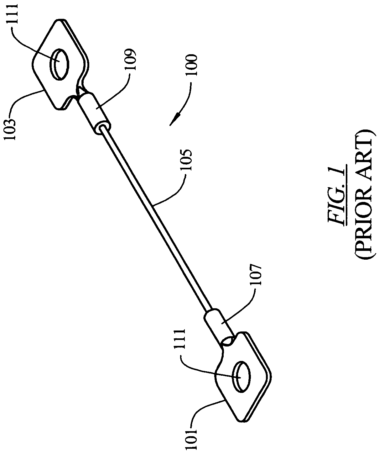
[0044]FIG. 1 shows a known wire-terminal assembly 100. The wire-terminal assembly 100 may be used to provide an electrical or mechanical connection between two components, such as components in a vehicle. The wire-terminal assembly 100 comprises electrical terminals or conduction pads 101 and 103 that are connected by conductor wire 105. The pads 101 and 103 are coupled to wire 105 by portions 107 and 109, respectively, which are crimped to the wire 105. The pads 101 and 103 each include a hole or opening 111 for attachment to a connection point through the use of a screw, threaded post, or the like, and secured through the use of a nut and a washer, not shown.

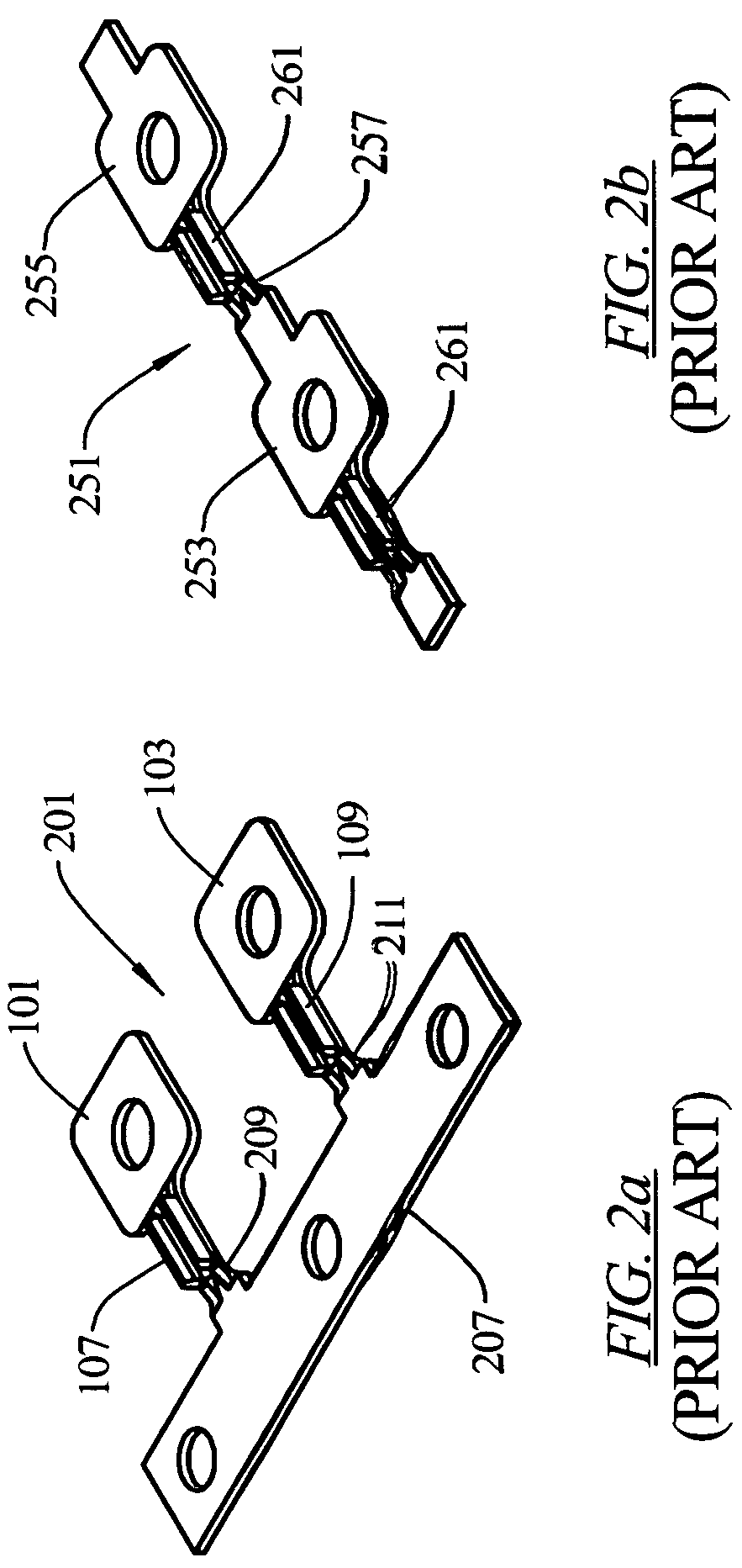
[0045]FIG. 2a shows a portion of a known supply reel 201 that includes conduction pads 101 and 103 connected by a carrier strip 207. Linkages 209 and 211 connect the conduction pads 101 and 103, respectively, to the carrier strip 207. FIG. 2b shows a portion of a known supply reel 251 that includes conduction pads 253 and 255 ...


PUM

PropertyMeasurementUnit
flexibleaaaaaaaaaa
forceaaaaaaaaaa
conductiveaaaaaaaaaa

Abstract

A self-locking wire terminal assembly and a shape memory wire termination system includes an electrical terminal constructed with spring legs which provide two opposing points of contact on a mating electrical conductive pin. The points of contact prevent the pin from being removed. The shape memory termination system is formed by electrically coupling a clip assembly to shape memory wire and to an electrical source. In one embodiment, the shape memory wire causes an actuator to activate when the shape memory wire dissipates electrical power. The terminal assemblies may be manufactured by assembling wire with conduction pads onto a continuous reel. The terminal assemblies may be formed from the reel by trimming wire and linkages between the conduction pads.

Description

CROSS REFERENCE TO RELATED APPLICATIONS[0001]This Non-Provisional Application claims benefit to U.S. Provisional Application Ser. No. 60 / 580,478, filed Jun. 17, 2004, and to U.S. Provisional Application Ser. No. 60 / 641,994, filed Jan. 7, 2005.FIELD OF THE INVENTION[0002]The present invention relates generally to an electrical connector assembly, and more particularly to a self-locking wire terminal assembly and a shape memory wire termination assembly.BACKGROUND OF THE INVENTION[0003]It is known that electrical terminal assemblies are used to connect electrical devices. In order to form these electrical terminal assemblies, an electrical conductor, such as a wire, is coupled to a pair of electrical terminals or pads. The electrical pads are typically supplied either loose or on reels. The reeled pads can be supplied either on a carrier strip or chained end-to-end. In order to assemble the electrical terminal assemblies, the pads must be removed from the carrier strip and the pads mu...

Claims


Application Information

Patent Timeline
Patent Type & Authority Patents(United States)
IPC IPC(8): H01R13/11F03G7/06H01H37/32H01H61/01H01H71/14H01R4/01H01R4/18H01R11/22H01R13/115H01R13/40
CPCH01R11/22H01R13/40H01R12/58H01H37/323H01H61/0107H01H71/145H01R4/01H01R4/188Y10T29/49185H01R12/515Y10T29/49147Y10T29/5137Y10T29/49151
Inventor IRISH, KENNETH G.TUREK, JAMES A.
Owner XEROX CORP
Why Eureka
Try Eureka