Methods for driving bistable electro-optic displays

a technology of electro-optic displays and displays, applied in the direction of non-linear optics, static indicating devices, instruments, etc., can solve the problems of inadequate service life of these displays, preventing their widespread use, and gas-based electrophoretic media being susceptible to the same types of problems

Inactive Publication Date: 2009-02-17
E INK CORPORATION
View PDF267 Cites 277 Cited by
  • Summary
  • Abstract
  • Description
  • Claims
  • Application Information

AI Technical Summary

Problems solved by technology

Nevertheless, problems with the long-term image quality of these displays have prevented their widespread usage.
For example, particles that make up electrophoretic displays tend to settle, resulting in inadequate service-life for these displays.
Such gas-based electrophoretic media appear to be susceptible to the same types of problems due to particle settling as liquid-based electrophoretic media, when the media are used in an orientation which permits such settling, for example in a sign where the medium is disposed in a vertical plane.
Indeed, particle settling appears to be a more serious problem in gas-based electrophoretic media than in liquid-based ones, since the lower viscosity of gaseous suspending fluids as compared with liquid ones allows more rapid settling of the electrophoretic particles.
Furthermore, it has now been found, at least in the case of many particle-based electro-optic displays, that the impulses necessary to change a given pixel through equal changes in gray level (as judged by eye or by standard optical instruments) are not necessarily constant, nor are they necessarily commutative.
Although these problems can be reduced or overcome by driving all pixels of the display to one of the extreme states for a substantial period before driving the required pixels to other states, the resultant “flash” of solid color is often unacceptable; for example, a reader of an electronic book may desire the text of the book to scroll down the screen, and may be distracted, or lose his place, if the display is required to flash solid black or white at frequent intervals.
Furthermore, such flashing of the display increases its energy consumption and may reduce the working lifetime of the display.
Another problem in driving bistable electro-optic displays is that small residual voltages across the electro-optic medium can persist after a transition waveform.

Method used


Image

  • Methods for driving bistable electro-optic displays
  • Methods for driving bistable electro-optic displays
  • Methods for driving bistable electro-optic displays

Examples


Embodiment Construction

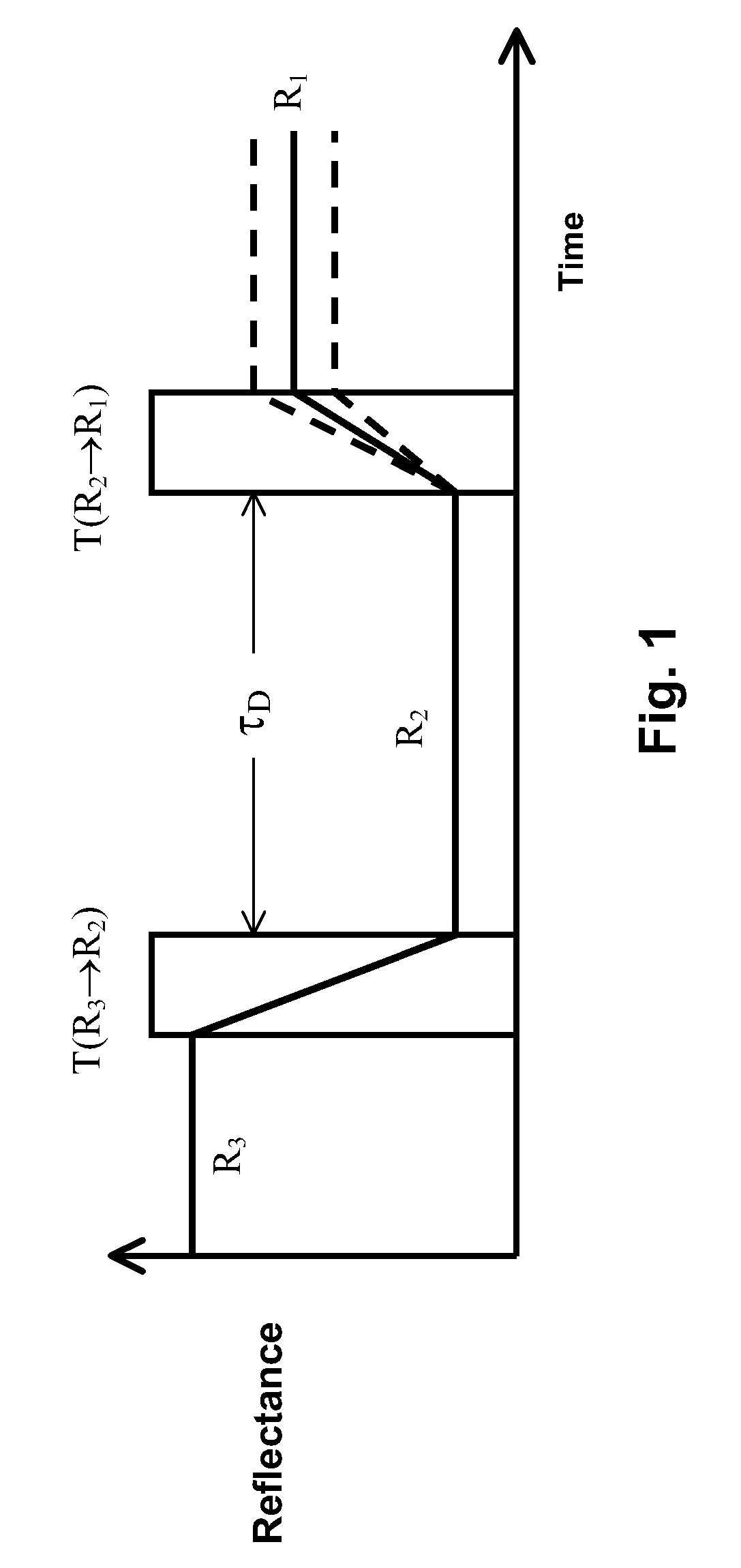
[0051]As already mentioned, the present invention provides various methods for driving bistable electro-optic displays, these methods being intended to reduce dwell time dependence (DTD). Although the invention is in no way limited by any theory as to its origin, DTD appears to be, in large part, caused by remnant electric fields experienced by the electro-optic medium. These remnant electric fields are residues of drive pulses applied to the medium. It is common practice to speak of remnant voltages resulting from applied pulses, and the remnant voltage is simply the scalar potential corresponding to remnant electric fields in the usual manner appropriate to electrostatic theory. These remnant voltages can cause the optical state of a display film to drift with time. They also can change the efficacy of a subsequent drive voltage, thus changing the final optical state achieved after that subsequent pulse. In this manner, the remnant voltage from one transition waveform can cause th...


PUM

PropertyMeasurementUnit
timeaaaaaaaaaa
timeaaaaaaaaaa
timeaaaaaaaaaa

Abstract

A bistable electro-optic display having at least one pixel is driven using a waveform V(t) such that:J=∫0T⁢V⁡(t)⁢M⁡(T-t)⁢ⅆt(where T is the length of the waveform, the integral is over the duration of the waveform, V(t) is the waveform voltage as a function of time t, and M(t) is a memory function that characterizes the reduction in efficacy of the remnant voltage to induce dwell-time-dependence arising from a short pulse at time zero) is less than about 1 volt sec.

Description

REFERENCE TO RELATED APPLICATIONS[0001]This application claims benefit of copending provisional Application Ser. No. 60 / 557,094, filed Mar. 26, 2004, and of copending provisional Application Ser. No. 60 / 560,420, filed Apr. 8, 2004.[0002]This application is related to copending application Ser. No. 10 / 065,795, filed Nov. 20, 2002 (Publication No. 2003 / 0137521), which itself claims benefit of the following Provisional Applications: (a) Ser. No. 60 / 319,007, filed Nov. 20, 2001; (b) Ser. No. 60 / 319,010, filed Nov. 21, 2001; (c) Ser. No. 60 / 319,034, filed Dec. 18, 2001; (d) Ser. No. 60 / 319,037, filed Dec. 20, 2001; and (e) Ser. No. 60 / 319,040, filed Dec. 21, 2001. The aforementioned copending application Ser. No. 10 / 065,795 is also a continuation-in-part of application Ser. No. 09 / 561,424, filed Apr. 28, 2000 (now U.S. Pat. No. 6,531,997), which is itself a continuation-in-part of application Ser. No. 09 / 520,743, filed Mar. 8, 2000 (now U.S. Pat. No. 6,504,524). The aforementioned applic...

Claims


Application Information

Patent Timeline
Patent Type & Authority Patents(United States)
IPC IPC(8): G09G3/36G02F1/141G09G3/34
CPCG09G3/344G09G2320/0257G09G2320/0204G09G2310/06
Inventor AMUNDSON, KARL R.
Owner E INK CORPORATION
Why Eureka
Try Eureka