Methods of printing filter material to fabricate color filter

a filter material and printing filter technology, applied in the direction of coatings, optical elements, instruments, etc., can solve the problems of limited application of electrodeposition coating technique, difficult subsequent coloring process, and relatively complex pigment-related methods

Inactive Publication Date: 2009-02-24
PALO ALTO RES CENT INC
View PDF23 Cites 4 Cited by
  • Summary
  • Abstract
  • Description
  • Claims
  • Application Information

AI Technical Summary

Problems solved by technology

However, the conventional pigment-related methods typically involve a relatively complex process, and they require at least three photomasks which must be precisely aligned to ensure good quality.
The disadvantages of the electrodeposition coating process are that it is necessary to perform a high precision patterning of the transparent electrode, and to pay meticulous attention during the subsequent process not to break the fine pattern, because otherwise, the subsequent coloring process will be rendered very difficult.
The electrodeposition coating technique is limited in its applications because it requires a substrate with a stripe pattern of conductive (ITO) film (the stripe pattern consists of a plurality of segregated parallel lines) for implementation, and it typically cannot be used without the stripe patterns.
Thus, the electrodeposition coating processes are suitable for the preparation of color filters for use in STN-LCDs, and have limited applications.
The electrodeposition lithographic method requires developer solutions at least three different levels of concentrations so as to selectively remove the exposed photoresist at different stages of the development process, thus it allows only a relatively narrow process window within which tolerance is acceptable, and there exist only very limited options in selecting an appropriate photoresist.
Additionally, only a limited number of options of photoresist-developer combinations can be utilized.
This is especially true when a positive photoresist is used, in which only cationic electrodeposition resins can be used and anionic cannot be used.
This problem is further complicated by the fact that the colored resin cannot be hardened by light or heat during the electrodeposition lithographic process so as to ameliorate the problem caused by the uncured colored resin.
Only negative photoresists can be used with an anionic electrodeposition resin; however, it is well known that negative photoresists do not provide the same dimensional precision as positive photoresists, and the trend in the industry is using positive photoresists.
Thus the electrodeposition lithographic method disclosed in the prior art, which, almost by default, requires the combination of positive photoresist and anionic colored electrodeposition resin, does not represent the best, or the most desired, choice.
However, it suffers the problems of poor dimensional precision, uniformity, smoothness, and reliability, and is not well accepted by the industry for making high quality electronic products.

Method used


Image

  • Methods of printing filter material to fabricate color filter
  • Methods of printing filter material to fabricate color filter
  • Methods of printing filter material to fabricate color filter

Examples


Embodiment Construction

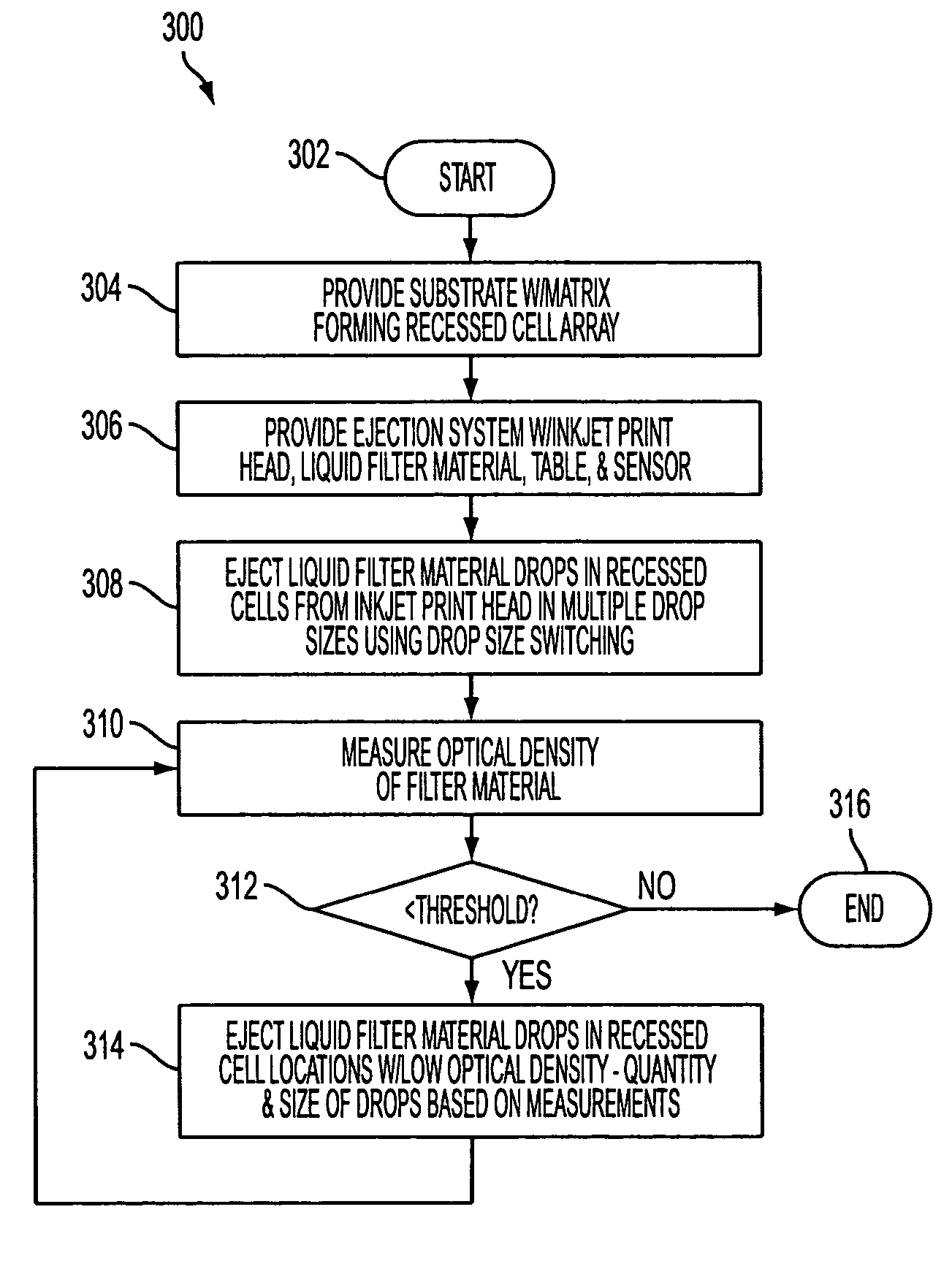
[0027]In general, drop size switching (DSS) techniques associated with inkjet printing have not been used previously to print filter material (e.g., red, green, and / or blue filter material) on a substrate in fabricating a color filter for a display device. A method for use of inkjet print heads (e.g., piezo, acoustic, thermal, etc.) with a DSS printing process reduces fabrication costs and improves the uniformity characteristics in printing filter material in fabrication of color filters for various types of display devices (e.g., liquid crystal displays (LCDs), light emitting diodes (LEDs), plasma display panel (PDP) devices, etc.). Use of the DSS printing process also reduces the fabrication time for a color filter, particularly where DSS printing replaces lithographic printing or photolithographic processes.

[0028]For example, piezo (e.g., piezoelectric, piezoceramic, etc.) print heads can operate in several droplet modes, depending on the character of the voltage waveform applied...


PUM

PropertyMeasurementUnit
particle sizeaaaaaaaaaa
diameteraaaaaaaaaa
diameteraaaaaaaaaa

Abstract

Several methods of printing filter material on a substrate to fabricate a color filter are provided. In one embodiment, the method includes: a) providing a substrate with a framework forming a cell, b) providing a liquid filter material ejection system with an inkjet print head, a liquid filter material, and a table supporting the substrate, and c) ejecting liquid filter material drops in the cell from the inkjet print head using a drop size printing process. The drops include smaller and larger drops. A color filter for a display device is also provided. In one embodiment, the color filter includes: a substrate, a framework attached to the substrate forming a cell, and a cured filter material fixed to the cell. The cured filter material is formed by ejecting multiple sizes of liquid filter material drops from an inkjet print head using a drop size switching printing process.

Description

BACKGROUND[0001]The exemplary embodiments disclosed herein relate to methods of printing filter material to fabricate a color filter. It finds particular application in conjunction with printing the red, green, and blue filter material to fabricate a color filter for a display, such as a liquid crystal display (LCD), and will be described with particular reference thereto. However, it is to be appreciated that the exemplary embodiments are also amenable to fabrication of color filters for other types of displays, display devices, and like applications.[0002]With the rapid growth of the information industry and continuous breakthroughs in the display technologies, a trend is becoming increasingly recognizable in that flat panel displays (FPD), which take up a much smaller space, are gradually taking the place of the traditional cathode ray tubes (CRT). Among the various flat panel displays, liquid crystal displays (LCD) have assumed a leading position, because of their light weight, ...

Claims


Application Information

Patent Timeline
Patent Type & Authority Patents(United States)
IPC IPC(8): G02F1/1335
CPCG02B5/208G02F1/133516B41J2/2128G02B5/201
Inventor ELROD, SCOTT A.
Owner PALO ALTO RES CENT INC
Why Eureka
Try Eureka