High contrast projection screen

a projection screen and high contrast technology, applied in the field of projection screens, can solve the problems of poor contrast of viewers of such images, interference from ambient reflection in well-lighted rooms, and image display on front projection screens, so as to reduce ambient light interference and reduce image brightness

Active Publication Date: 2009-02-24
ISHII FUSAO
View PDF6 Cites 10 Cited by
  • Summary
  • Abstract
  • Description
  • Claims
  • Application Information

AI Technical Summary

Benefits of technology

[0010]It is an aspect of the present invention that the front-end projection screen for reflecting the incident image light beams has circular ridges formed on a flat surface with these the reflection portions of the ridges form a combined Fresnel surface to reflect all the incident beam from a focal point of the Fresnel surface to horizontal parallel light beams directing to the viewer. Reduction of image brightness due to reflection of only a portion of the lights as that disclosed in conventional polarized reflection screen can therefore be eliminated while the ambient light interferences can be reduced.
[0011]In another aspect, the present invention provides a front-end projection screen for reflection the incident image light beams that has micro-ridges formed with a reflection portion located on the bottom facing the image light source disposed at the bottom of the screen and a non-reflection top portion. The non-reflection top ridge surfaces are coated with a non-reflecting dark material such that the ambient light mostly incident from the lights typically disposed on the ceiling can be eliminated. This method can avoid the interference of the ambient light that may project to the screen from top, side and even from the direction of the viewers, e.g., from the front direction of the reflection screen.
[0012]In yet another aspect, the present invention provides a front projection display system with the image light source disposed at the bottom of the screen to project an image onto a reflecting screen. The reflecting screen has micro-ridges with a bottom reflecting portions facing the incident image light. The bottom portions of the micro-ridges are further combined to form a Fresnel surface to reflecting all the incident light beam as horizontal reflecting light to a viewer to provide clear and high quality image display with the image light source located at the focal point of the Fresnel surface with a short distance away from the projection screen.
[0013]In yet another aspect, the present invention provides a method of manufacturing a front-end projection screen by pressing a UV curable surface into circular ridges with the bottom portions of the micro-ridges forming a Fresnel surface. The projection screen can therefore be produced very economically without requiring complicate and sophisticate manufacturing processes.

Problems solved by technology

Image display on the front projection screens often encounters a difficulty that the viewers of such image often experience a poor contrast due to the interferences from the ambient lights reflected from the projection screen.
The interferences from ambient reflection is especially pronounced in a well-lighted room.
However, the ambient reflections often cause uncomfortable glares in a viewer's eyes when the front projection screen is projected with the high power projectors.
Conventional technologies for providing high contrast projection screens are still limited by the difficulties that the screens are either manufactured with multiple layers or requiring special processes or materials.
Such multiple layered screen or specially processed surface are usually complicated to fabricate and very costly.
Front end projection display with reflective type of display screens are therefore limited by these technical difficulties and also by the economic limitations since a it is very expensive to provide the high contrast projection screen with ambient light elimination or reduction.
Such systems however are more costly and difficult to implement due to the several components required to combine into a low contrast video projection system.
The polarized projection screen further reduces the light intensity and leads to an undesirable effect of reducing the brightness of the display images due to the fact that only the light beams of specific polarization are reflected.
With the polarizer, this method reduces the ambient light by half, but it does not provide a complete solution because there are still significant interferences caused by the remaining unnecessary ambient light.
Again, this multiple layered screen with polarization reflection is more costly and complicate to implement.
Furthermore, the polarization projection as discussed above leads to reduced brightness of display images thus degrades the image quality Again, like what are discussed above, by applying the polarizer, this method reduces the ambient light by half, but it does not provide a complete solution due to the significant interferences caused by the remaining unnecessary ambient light.
However, as can be clearly understood, such multiple layered projection screen embedded with beads are costly and inconvenient to implement.
Furthermore, the horizontal ridges as disclosed can only reduce the ambient interferences for light beams incident from above the screen.
Therefore, the contrast of image display can only be partially improved due to the limited reductions of ambient reflections.
Such specialized production method however requires special processing equipment and materials thus greatly increase the cost and manufacturing complexities of the projection screen.
Therefore, the projection screen with a wedge surface when a light source is located near a viewer's area for projecting image light horizontally to the reflecting screen even with wedge to reduce the ambient reflection is not sufficient to resolve the problems of ambient light interferences.
However, these inventions have not addressed and provided direct resolutions for a person of ordinary skill in the art to overcome the above-discussed limitations and difficulties.

Method used


Image

  • High contrast projection screen
  • High contrast projection screen
  • High contrast projection screen

Examples


Embodiment Construction

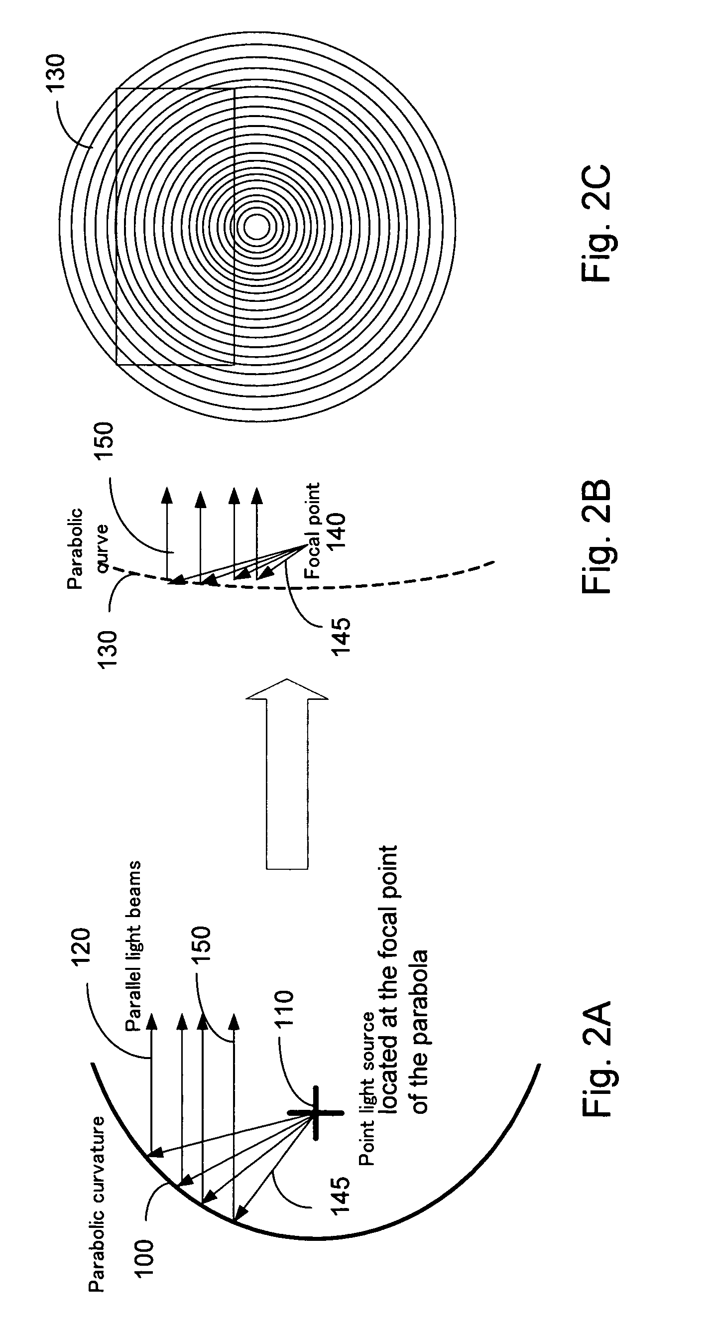
[0023]FIG. 2A shows a mirror 100 with parabolic curvature that received light projected from a light source 110. The light source 110 is located at the foal point of the parabola and the reflected light 120 from the parabolic mirror are all directed in parallel along a horizontal direction to a viewer. Therefore, theoretically, a reflective projection screen with a parabolic surface such as the mirror 100 would be most suitable to function as a projection screen for a front-end projection display system. However, a viewer does not feel comfortable looking at a parabolic screen. Furthermore, a parabolic screen is more difficult and costly to manufacture. is difficult to manufacture.

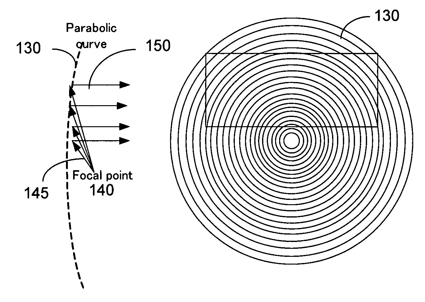
[0024]FIGS. 2B and 2C are cross sectional view and front view of a Fresnel mirror 130 with parabolic curvature according to an embodiment of this invention. The Fresnel mirror 130 is supported on a substantially flat and thin surface. The Fresnel mirror 130 achieves the same results as shown in FIG. 1B whe...


PUM


Abstract

An image display system includes a reflecting screen that has a reflecting surface. The reflecting surface includes micro-ridges having a plurality of reflecting ridge-surfaces wherein the reflecting ridge-surfaces constituting a Fresnel mirror whereby the reflecting ridge-surfaces reflecting parallel reflecting light beams for all incident light beams projected from a light source located at a focal point of the Fresnel mirror. The micro-ridges further include a plurality of darkened ridge-surfaces with reduced reflectance for reducing ambient reflections. The micro-ridges further constitute a continuous concentric ridge having the reflecting ridge-surfaces facing a bottom direction toward the focal point of the Fresnel mirror for disposing a light source near a bottom location of the projecting screen. The continuous concentric ridge further has reduced reflectance ridge-surfaces facing a top direction away from the focal point of the Fresnel mirror.

Description

TECHNICAL FIELD[0001]This invention relates to display system for projecting an image on a screen to display the image on the screen. More particularly, this invention relates to projection screen with improved contrast by directing the ambient reflection lights away from a viewer thus totally eliminating ambient interferences.BACKGROUND ART[0002]Image display on the front projection screens often encounters a difficulty that the viewers of such image often experience a poor contrast due to the interferences from the ambient lights reflected from the projection screen. The interferences from ambient reflection is especially pronounced in a well-lighted room. For this reason, it is often required to turn off the light in a room to provide a better view of the displayed image. One method to overcome the poor view of image is to project the image with higher luminance. However, the ambient reflections often cause uncomfortable glares in a viewer's eyes when the front projection screen ...

Claims


Application Information

Patent Timeline
Patent Type & Authority Patents(United States)
IPC IPC(8): G03B21/56G03B21/60
CPCG03B21/56
Inventor ISHII, FUSAO
Owner ISHII FUSAO
Why Eureka
Try Eureka