Three-dimensional imaging system

Active Publication Date: 2018-03-29
WILLDEN JEREMY PAUL
View PDF4 Cites 4 Cited by
  • Summary
  • Abstract
  • Description
  • Claims
  • Application Information

AI Technical Summary

Benefits of technology

[0029]Traditional 3D movie projection requires that each viewer wear special glasses that separate the left and right eye images. The glasses reduce the image brightness. This new method of 3D simulation actually produces a large number of viewing image angles. This system uses a mirror-like screen (or essentially transparent refractive screen) so the image is far brighter than with traditional methods. This results in potential energy savings for the projection system, and/or allows far smaller pixels to be used, improving spatial resolution while maintaining high image brightness. This suggests that the screens will often be custom-generated for a particular venue—the location of the screen and the seats will be modeled and the shape of the reflective or refractive elements will be adjusted to point the pixels to the optimum locations, thus optimizing the experience for the viewers. It is not necessary that the various viewing angles be “evenly spaced” along the horizontal and vertical axes. In many cases, the best viewing experience will dictate that the viewing angles be distributed to fill the “viewing cone” that the audience occupies. In a movie theater, for example, the viewing angles should be distributed to cover the area of the seats, not the walls nor ceiling.
[0030]The invention can be implemented in several embodiments. One embodiment has a front projection screen with small protrusions pointing out towards the viewer or small indentations pointing away from the viewer, the protrusions and indentations having an egg carton bottom-like configuration. The screen is highly reflective, generally a mirror-like finish. An alternative embodiment uses a rear projection screen using the same egg carton bottom-like configuration, but employing a translucent lens array molded from a high-quality plastic or glass. The image is projected from behind and each

Problems solved by technology

That is because non-coincident red, green and blue sub-pixels result in color-banded moiré patterns that detract fr

Method used


Image

  • Three-dimensional imaging system
  • Three-dimensional imaging system
  • Three-dimensional imaging system

Examples


Embodiment Construction

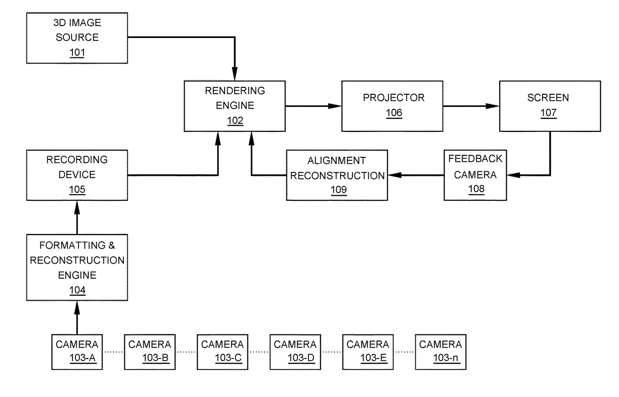
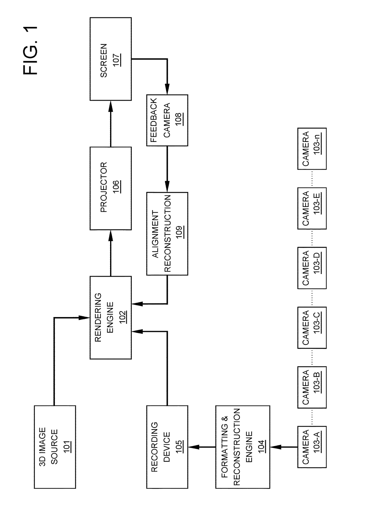
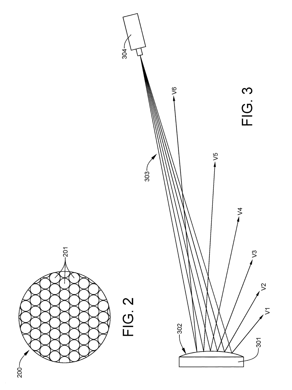
[0053]The present invention provides a novel way of simulating three-dimensional images on a display screen without the need for a viewer to wear image-splitting glasses. Although it incorporates elements of both lenticular printing and holography, it is likely best characterized as a super set of lenticular printing. The invention can be used to portray both individual three-dimensional photographs or three-dimensional movies. Given that the manufacturing methods for monitors, projectors, DLP® imaging systems, and other displays is likely to continue to produce improved resolutions with time, it will become practical to use lensing systems to reflect or refract small collections of pixels at various angles to produce 3D “holographic” screens and display systems. The effective image resolution is reduced from the native screen resolution, but to the extent that the native resolutions are unnecessarily high for human viewing, spatial (angular) resolution can be improved or “traded of...


PUM


Abstract

A three-dimensional imaging system relies on effective native image resolution reduction in order to provide an array of pixel clusters, or voxels, with each pixel of the voxel representing a pixel of the image from a unique viewing angle. A 16-megapixel screen having 16-pixel voxels results in a screen having an image capacity downgraded to a 1-megapixel screen capable of showing sixteen different viewing angles. The system can be set up as a rear-projection screen or as a reflective screen illuminated by a front projector. The invention is best implemented with projectors and screens that represent all colors at a single physical location, such as a 3-panel LCD color-combinant projector or a DLP projector, either single or triple chip type. When the RGB sub-pixels are non-coincident, the viewers will see color artifacts that detract from the viewing experience.

Description

RELATED APPLICATIONS[0001]This application claims a priority date of Sep. 29, 2016, based on the filing of the identically-titled provisional patent application No. 62 / 401,456.FIELD OF THE INVENTION[0002]The present invention relates to projection screens and, m ore particularly, to projection screens capable of displaying three-dimensional images.BACKGROUND OF THE INVENTION[0003]This focus of this invention is the simulation of three-dimensional images on a display screen. Traditional three-dimensional simulation requires each viewer to wear glasses that separate left and right eye images. There are at least two drawbacks to this traditional approach. The first is that the glasses reduce the image brightness. The second is that the glasses approach discriminates against persons having monocular vision. Whereas those having monocular vision can obtain a three-dimensional perspective of the world around them by movement within their environment, simulation of three-dimensional images...

Claims


Application Information

Patent Timeline
IPC IPC(8): G02B27/22G03B21/625G03B35/26H04N13/00H04N13/122
CPCG02B27/2235G03B21/625G03B35/26H04N13/0018G03B21/602G03B35/18H04N13/302H04N13/243H04N13/324H04N13/111H04N13/363H04N13/366H04N13/327G02B30/35H04N13/122G02B30/34
Inventor WILLDEN, JEREMY PAUL
Owner WILLDEN JEREMY PAUL
Why Eureka
Try Eureka