Electro-optical device and electronic apparatus

Inactive Publication Date: 2010-03-04
SEIKO EPSON CORP
View PDF1 Cites 3 Cited by
  • Summary
  • Abstract
  • Description
  • Claims
  • Application Information

AI Technical Summary

Benefits of technology

[0015]Accordingly, according to the electro-optical device of the invention, since it is possible to reduce the brightness difference and the color density difference attributable to the difference between the optical path lengths of the first and second display rays, it is possible to reduce unevenness in the brightn

Problems solved by technology

In particular, in the electro-optical devices, such as a liquid crystal display device, which are mounted in electronic apparatuses, such as an HDM or an EVF, in which the position of the view point with respect to the display region at which the image is displayed is fixed in a plan view and which are used u

Method used


Image

  • Electro-optical device and electronic apparatus
  • Electro-optical device and electronic apparatus
  • Electro-optical device and electronic apparatus

Examples


Example

[0030]Hereinafter, embodiments of an electro-optical device and an electronic apparatus according to the invention will be described with reference to the accompanying drawings.

1. Electronic Apparatus

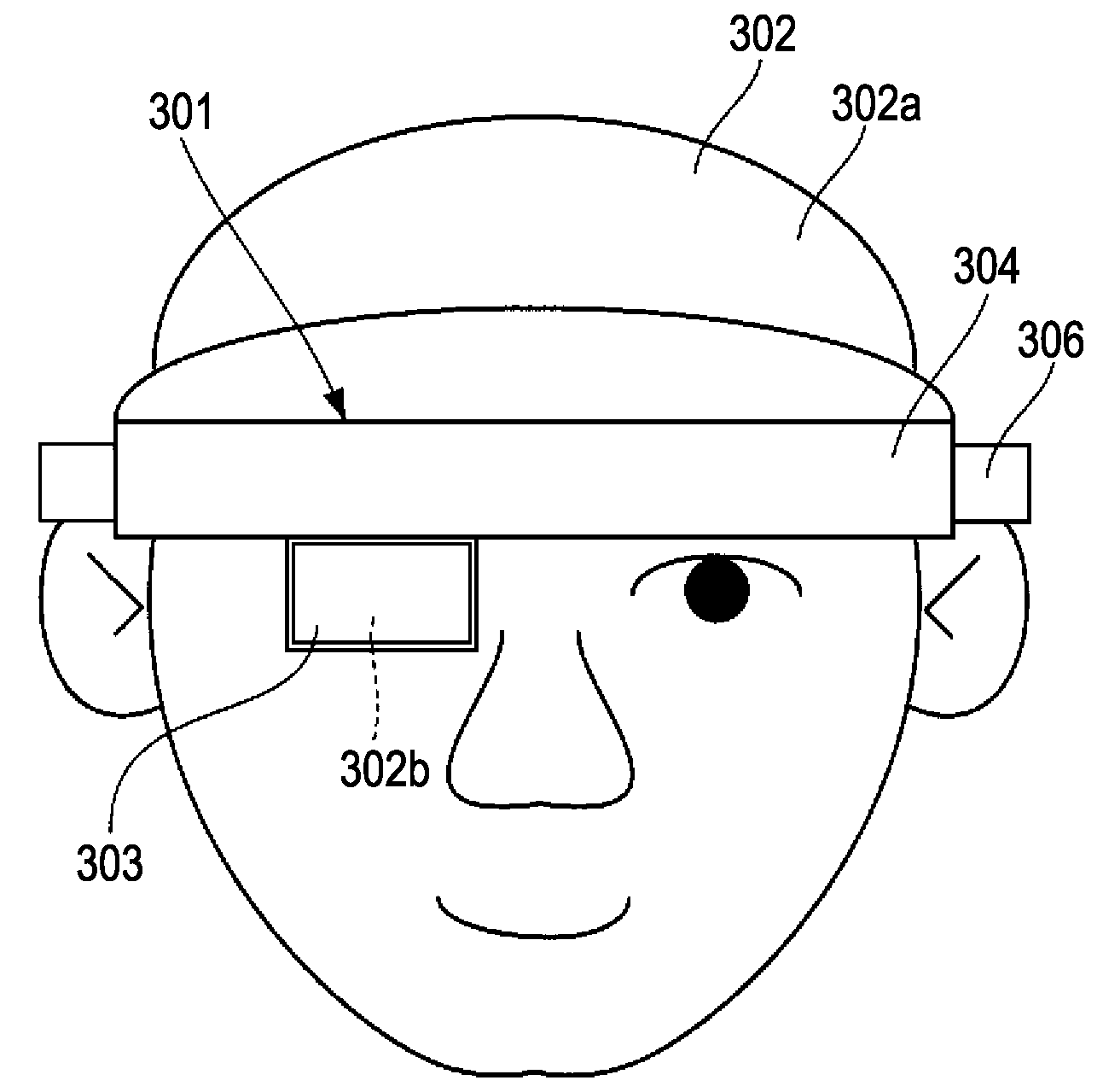
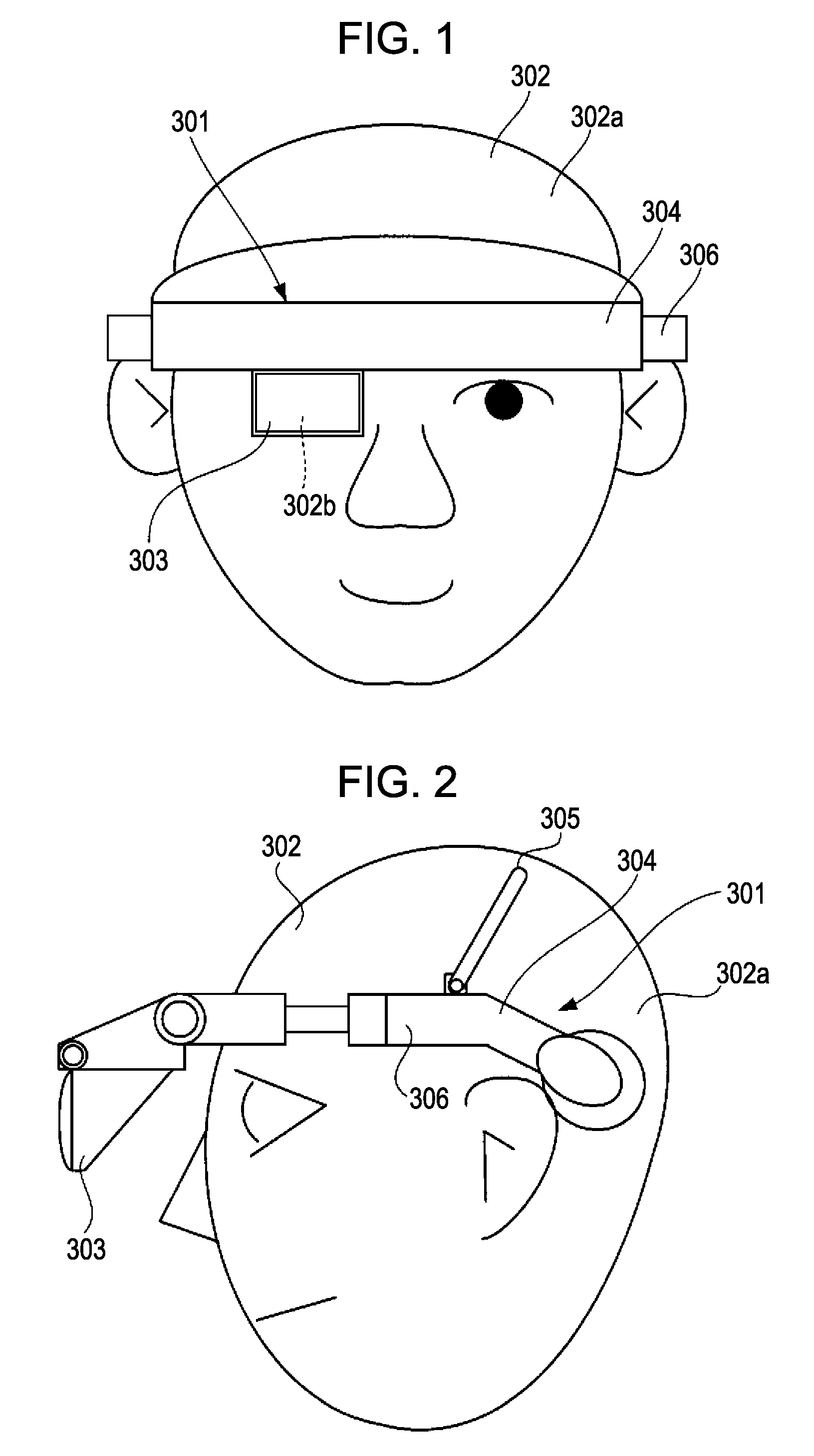
[0031]First, an HMD which is an example of an electronic apparatus according to the invention will be described with reference to FIGS. 1 and 2. FIG. 1 is a front view illustrating a state in which the HMD according to one embodiment is mounted on a head portion. FIG. 2 is a side view illustrating a state in which the HMD according to the embodiment is mounted on the head portion.

[0032]As shown in FIGS. 1 and 2, the HMD 301 is used in a state in which the HMD 301 is mounted on a head portion 302a of a viewer 302 who sees an image displayed by the HMD 301. The HMD 301 has a display portion 303 positioned in front of a right eye 302b of the viewer 302. The HMD 301 displays an image at an image display region of the display portion 303 at the time of operation. The viewer 302 sees an image...


PUM


Abstract

An electro-optical device, in which the position of the view point of a viewer who sees the display region on a substrate is fixed to a predetermined position within the display region in a plan view, includes a first color filter which overlaps a first pixel region disposed at the predetermined position among a plurality of pixel regions constituting the display region and a second color filter which overlaps a second pixel region disposed closer to an outer side of the display region than the predetermined position among the plurality of pixel regions, in which the hue of the first color filter is the same as that of the second color filter, and thicknesses of the first and second color filters are set such that a difference in density of color between a first display ray which has passed through the first color filter and a second display ray which has passed through the second color filter is small when measuring the first display ray and the second display ray at the position of the view point.

Description

BACKGROUND[0001]1. Technical Field[0002]The present invention relates to a technique of an electro-optical device which can perform a color display and a technique of an electronic apparatus equipped with such an electro-optical device, such as a head mounted display (hereinafter, referred to as HMD) or an electronic viewfinder (hereinafter, referred to as EVF).[0003]2. Related Art[0004]In a liquid crystal device which is an example of such an electro-optical device, a color image is displayed by three kinds of colored rays, a red ray(R), a green ray(G), and a blue ray(B) which have passed through plural kinds of color filters. JU-A-H6-55137 discloses a liquid crystal display device capable of reducing the occurrence of color mixture attributable to the thickness of the glass substrate on which the color filters are provided. JP-A-H11-38426 and JP-A-2005-257758 disclose display devices capable of inhibiting a lowering of the aperture ratio which can occur according to the positions ...

Claims


Application Information

Patent Timeline
IPC IPC(8): G09G5/00
CPCG02B27/017G02B27/0172G02B2027/0187G02F2203/18G02F1/133516G02F2202/40G02F1/133514G02B5/20G02F1/1335
Inventor KOIKE, SATOFUMI
Owner SEIKO EPSON CORP
Why Eureka
Try Eureka