Arrangement for two-or three-dimensional display

a two-or-three-dimensional display and arrangement technology, applied in the field of arrangement for two-or-three-dimensional display, can solve the problems of disturbingly strong moiré effects in the 3d display, the brightness is reduced in both the 2d and 3d display, and the presentation of common text or two-dimensional graphs is allowed but a limited extent, so as to reduce image brightness, reduce viewing distance, and high resolution

Inactive Publication Date: 2012-08-07
PHOENIX 3D INC
View PDF18 Cites 6 Cited by
  • Summary
  • Abstract
  • Description
  • Claims
  • Application Information

AI Technical Summary

Benefits of technology

[0017]Based on the above, it is the purpose of the present invention to create an arrangement of the kind mentioned at the beginning, that can be implemented by simple means. In the 3D mode, the arrangement is intended to present an image that can be seen in three dimensions by several viewers at a time without the need of extra aids. In the 2D mode, the intention is to present an image with the best possible resolution, preferably with full resolution. Image brightness is intended to be equal in the 2D and 3D mode, preferably without any reduction of image brightness in the 3D mode caused by the 2D / 3D switching means in comparison to a pure 3D display. As another purpose, the present invention is intended to implement typical—preferably small—viewing distances, especially with 3D displays of high resolution. The arrangement to be created should preferably have the same ambient light compatibility as a pure 2D display.

Problems solved by technology

These arrangements, however, frequently allow but a limited presentation of common text or two-dimensional graphs, which is the case, e.g., with U.S. Pat. No. 5,457,574 and U.S. Pat. No. 5,606,455.
As a disadvantage, though, the light has to penetrate two LCD panels, i.e. through a great number of devices as, e.g., polarizing filters, liquid crystal layers and other component parts such as carrier substrates, so that brightness is reduced in both 2D and 3D display.
The downside is that it is a two-channel 3D display for a single viewer, who has to occupy a fixed viewing position at that.
Furthermore, a viewer who is not in the correct viewing position depthwise in front of the 3D display will see disturbingly strong moiré effects.
Besides, manufacturing the device takes much effort and cost.
As a further disadvantage, the insertion of a switchable diffusion disk increases the distance between the illuminating module and the image-reproducing panel, which inhibits normal viewing distances especially in 3D displays with small pixels and / or high resolution.
Other drawbacks are sensitivity to dust, and increased reflection losses.
The disadvantage of this arrangement is that the luminance of the 2D illumination cannot be made sufficiently homogeneous.
Moreover, if a commercial light guide is used for 2d illumination, its macroscopic structure is visible to the viewer or viewers, as a rule, creating a disturbing pattern, whereas an invisible microscopic structure is difficult and expensive to manufacture.
The disadvantage of this arrangement is that it requires an inherent light source for light of parallel rays, so that, in strict sense, there is no 3D viewing space but only a single, fixed 3D viewing position.
Moreover, parallel radiation requires a complicated light guide in the “side light mode” used in this arrangement.
A complicated, expensive “side light” would also be required for adding a “parallelization structure” to the light guide face opposite the outcoupling face, i.e. the one facing the viewer.
With 3D display, this would give rise to varied degrees of image blurring, especially when viewed obliquely.
The downside of this arrangement is that resolution in the 2D mode is very poor and “full resolution” cannot be reached in that mode.
In addition, the manufacture of such a lenticular screen is difficult and expensive, and because of the added switchable diffusion properties it has further drawbacks.
Further, it does not reach the ambient light compatibility of conventional 2D displays.
Therefore, the diffusing layer must necessarily impair the 2D image on the image display means and cannot cancel the image-separating effect of the lenticular screen.
As a result, text presented in the 2D mode with these arrangements remains illegible; furthermore, they do not reach the ambient light compatibility of conventional 2D displays.

Method used


Image

  • Arrangement for two-or three-dimensional display
  • Arrangement for two-or three-dimensional display
  • Arrangement for two-or three-dimensional display

Examples


first embodiment

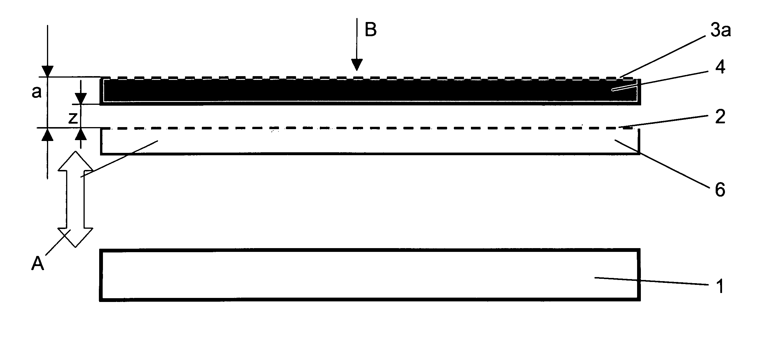
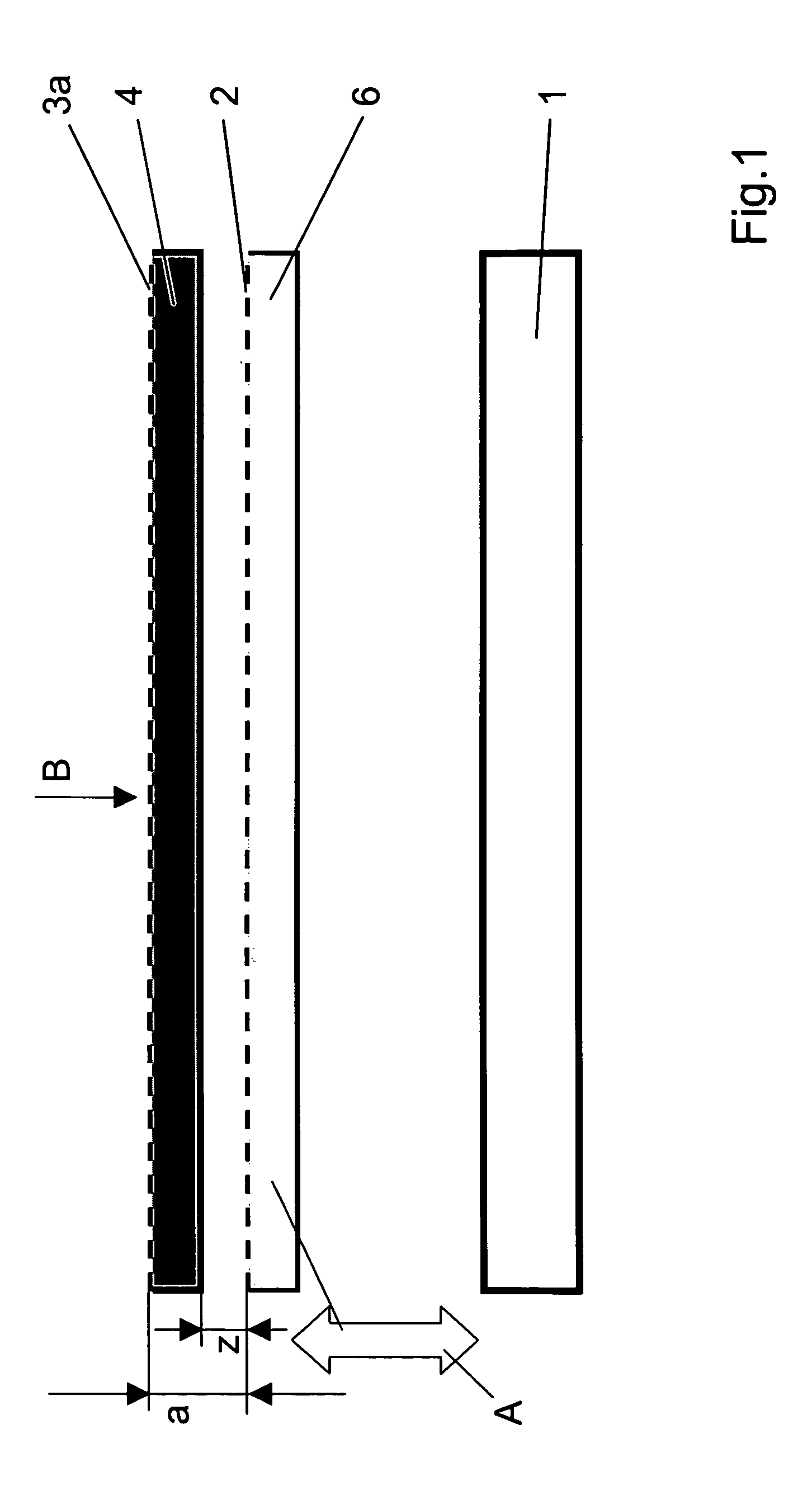
[0081]FIG. 1 is a sketch illustrating the principle of a first embodiment version of the arrangement according to the invention. As shown in FIG. 1, the arrangement comprises an illuminating device 1 emitting light distributed over an area, a filter array 2 arranged before the illuminating device 1 ((in viewing direction B)) and intended to impart a structure to the light originating from the illuminating device 1, a diffusing layer 3a arranged before the filter array 2 and the image display device 4 ((in viewing direction B)), and, as an example, a transmissive image display device 4 arranged behind the diffusing layer 3a ((in viewing direction B)).

[0082]The diffusing layer 3a at the image display device is preferably a common antiglare matte finish as it is typical of LCD panels. The image display device 4 is rigidly connected with the illuminating device 1 through subassemblies not shown on the drawing. The filter array 2 is, for example, laminated onto a transparent substrate 6....

second embodiment

[0088]In a second embodiment version of the arrangement according to the invention, which is shown in FIG. 4, there are again provided (in the order of the viewing direction) a diffusing layer 3a, an image display device 4, a filter array 2 applied on a transparent substrate 6, and an illuminating device 1.

[0089]Unlike the first embodiment version, here the transparent substrate 6 and the filter array 2 are rigidly connected to the illuminating device 1, whereas the transparent substrate 6, the filter array 2 and the illuminating device 1 are arranged to be jointly movable for the purpose of varying the distance a, as again indicated by the arrow A. This corresponds to an embodiment according to version 2a. Here again, the movement can be implemented by very simple means.

[0090]By varying the distance a it is possible to set a 3D display mode (second position of the arrangement) as shown in FIG. 5, and a 2D display mode (first position of the arrangement) as shown in FIG. 6.

[0091]The...

third embodiment

[0092]Let a third embodiment version be explained with reference to FIG. 7. Here, the order in which the components are arranged corresponds to that in the embodiment versions already described, with the difference, however, that the image display device 4 and the diffusing layer 3a are arranged to be jointly movable for the purpose of varying the distance a, whereas a subassembly consisting of filter array 2, transparent substrate 6 and illuminating device 1 is relatively at rest or is attached in a fixed position relative to the chassis. This corresponds to the embodiment according to version 3a.

[0093]Analogously to the embodiment versions already described, the distance a shown in FIG. 8 illustrates a 3D viewing mode, and that shown in FIG. 9 illustrates a 2D viewing mode.


PUM


Abstract

An arrangement for the display of images with selectable three-dimensionally visible or two-dimensional modes, including an illuminating device a filter array to impart a structure to the light a diffusing layer, and a transmissive image display device, with a variable distance a between the filter array and the diffusing layer, so thatin a first position, the structure imparted by the filter array is essentially cancelled due to the light diffusion effect of the diffusing layer, and a two-dimensional image is shown, andthe structure imparted by the filter array is essentially not cancelled, so that the image display device shows a three-dimensional image.

Description

FIELD OF THE INVENTION[0001]The invention relates to an arrangement for the display of images with selectable three-dimensionally visible or two-dimensional modes. It relates to autostereoscopic screens that optionally display a two-dimensional image of the usual quality.BACKGROUND OF THE INVENTION[0002]In the course of research in the field of autostereoscopic display, a great number of methods and arrangements have been developed, which give impressions of space to one or several viewers. These arrangements, however, frequently allow but a limited presentation of common text or two-dimensional graphs, which is the case, e.g., with U.S. Pat. No. 5,457,574 and U.S. Pat. No. 5,606,455. For users it is of advantage, though, if they can switch between 3D display not requiring special eyeglasses and high-resolution, least-impaired 2D display on one and the same device.[0003]Means used for the optical display of the perspective views of an object in autostereoscopic presentation include,...

Claims


Application Information

Patent Timeline
Patent Type & Authority Patents(United States)
IPC IPC(8): G02B27/22G02B27/02H04N13/00H04N13/04
CPCH04N13/0454H04N13/0456H04N13/359H04N13/361
Inventor TZSCHOPPE, WOLFGANGBRUEGGERT, THOMASKLIPPSTEIN, MARKUSRELKE, INGOHOFMANN, UWE
Owner PHOENIX 3D INC
Why Eureka
Try Eureka