Backlight unit in display device and liquid crystal display device therewith

a display device and liquid crystal display technology, applied in static indicating devices, instruments, mechanical devices, etc., can solve the problems of increased power consumption, weight and bulk of crt, and inability to meet the demand for small sized light weight products, etc., to achieve the effect of improving the display performan

Active Publication Date: 2009-03-17
LG DISPLAY CO LTD
View PDF10 Cites 14 Cited by
  • Summary
  • Abstract
  • Description
  • Claims
  • Application Information

AI Technical Summary

Benefits of technology

[0084]An object of the present invention is to provide a backlight unit in a display device, in which light leakage to an adjacent region other than a driving region is suppressed in driving a frame divided by DDAM in an FS driving method for improving a display performance, and a liquid crystal display device therewith.

Problems solved by technology

The CRT, however, fails to deal with the demand for small sized light weight products due to the weight and bulk of the CRT itself.
Accordingly, under the trend that various electronic products become smaller and lighter, the CRT has certain limitations in view of its weight and bulk.
First, the low light transmittivity of the color filter layer of below 33%, with a great loss of the light, requires making the backlight brighter, which in turn leads to a greater power consumption.
Second, since the color filter layer is very expensive in comparison to other materials, the production cost of the LCD increases.
Although the FS type was suggested around 1960, the practical application of the FS type has been difficult to achieve because technologies on a fast response liquid crystal mode, and a light source that meets the fast response are required to follow thereafter.
The direct type backlight unit has lamps arranged on a flat surface, but has a limitation in fabrication of thin LCD because it is required to maintain a gap between the lamps and the liquid crystal panel for preventing a form of the lamp from showing on the liquid crystal panel, and to arrange light spreading means for uniform distribution of light on the whole device.
Moreover, the greater the size of the panel, the larger the area of a light emissive surface of the backlight unit.
In the meantime, the edge type backlight unit having lamps arranged at an outer side for spreading a light to the entire surface of the device by using a light guiding plate, has a problem of poor luminance because the light is required to pass the light guiding plate.
The direct type backlight unit, mostly used in a display device that regards the luminance important, has a high power consumption because the direct type itself is thick and spreads light effectively for maintaining uniformity of the luminance.
If tLC is reduced which leads to prolonging the actual response time period of the assigned liquid crystal beyond the allotted response time period of the assigned liquid crystal, the backlight is lit before the assigned liquid crystal is rearranged properly, which causes a problem of non-uniform distribution of a picture color.
The related art FS driving method has in general a slow liquid crystal response speed such that it is difficult to drive all the gate lines within one frame.
However, at the time of the sequential driving by sequential lighting of one of the R, G, B LED lamps 73 relevant to a divided region of the light guiding plate 71 to be driven in succession (driven by DDAM), light leakage to the adjacent regions of the light guiding plate and the liquid crystal display panel other than the driving region drops the display performance and deteriorates the quality of the image being displayed.

Method used


Image

  • Backlight unit in display device and liquid crystal display device therewith
  • Backlight unit in display device and liquid crystal display device therewith
  • Backlight unit in display device and liquid crystal display device therewith

Examples


Embodiment Construction

[0108]Reference will now be made in detail to the preferred embodiments of the present invention, examples of which are illustrated in the accompanying drawings. Wherever possible, the same reference numbers will be used throughout the drawings to refer to the same or like parts.

[0109]A backlight unit in a display device in accordance with a first preferred embodiment of the present invention has a plurality of light guiding plates corresponding to divided regions of the display screen.

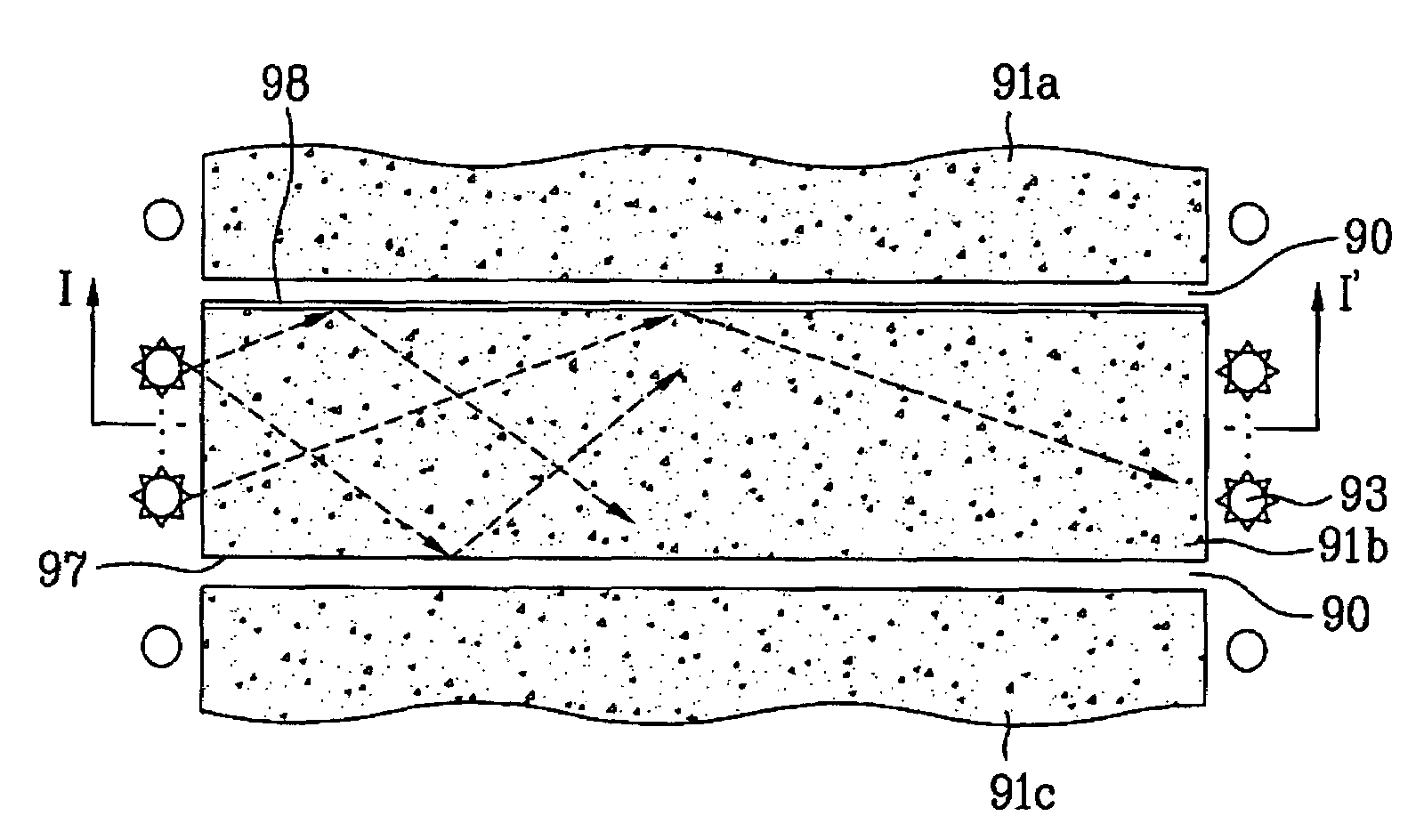
[0110]As an example, FIG. 8 illustrates a perspective view of an FS type backlight unit in accordance with the first preferred embodiment of the present invention, FIG. 9A illustrates a plan view showing the driving of the backlight unit in FIG. 8 in accordance with the first preferred embodiment of the present invention, and FIG. 9B illustrates a sectional view across the line I-I′ in FIG. 9A.

[0111]The present invention suggests driving a display region with the display region divided into ‘n’ sub-re...


PUM

PropertyMeasurementUnit
light transmittivityaaaaaaaaaa
refractive indexaaaaaaaaaa
weightaaaaaaaaaa

Abstract

A backlight unit in a display device having a Divided Display Area Method (DDAM) of a Field Sequential (FS) driving method applied thereto is provided. The backlight unit includes first to (n)th light guiding plates for field sequential drive, and a plurality of light sources arranged at at least one side of the first to (n)th light guiding plates at certain intervals.

Description

CROSS-REFERENCE TO RELATED APPLICATIONS[0001]This application claims the benefit of Patent Application No. P2003-98938, filed on Dec. 29, 2003 in Republic of Korea, which is hereby incorporated by reference.BACKGROUND OF THE INVENTION[0002]1. Field of the Invention[0003]The present invention relates to backlight units, and more particularly, to a backlight unit in a display device having a Divided Display Area Method (DDAM) of a Field Sequential (FS) driving method applied thereto, in which a display area is divided into sections in driving the display area, and to a liquid crystal display device therewith.[0004]2. Discussion of the Related Art[0005]As one of display devices used generally, CRTs (Cathode Ray Tubes) are mostly used, starting from TV receivers to monitors in measuring instruments, information terminals, and the like. The CRT, however, fails to deal with the demand for small sized light weight products due to the weight and bulk of the CRT itself.[0006]Accordingly, und...

Claims


Application Information

Patent Timeline
Patent Type & Authority Patents(United States)
IPC IPC(8): G09G3/36F21V8/00G02F1/13357G02F1/1335
CPCG02B6/0043G02B6/0055G02B6/0068G02F2001/133622G02F1/133622G02F1/1335
Inventor YOO, JANG JINWOO, JONG HOON
Owner LG DISPLAY CO LTD
Why Eureka
Try Eureka