Coupling of the cartridge of a cutter holder for industrial cutting

a technology of industrial cutting and cartridges, which is applied in the direction of metal sawing equipment, sawing equipment, shearing equipment, etc., can solve the problems of increased wear of the device, increased mechanical stress on the cutter holder, and occurrence of dangerous weaknesses

Active Publication Date: 2009-03-31
ZINCOMETAL
View PDF7 Cites 3 Cited by
  • Summary
  • Abstract
  • Description
  • Claims
  • Application Information

AI Technical Summary

Benefits of technology

[0007]The aim of the present invention is to provide a system for engaging and locking the cartridge on the cutter holder body which allows a symmetrical distribution of forces on both sides of the head portion of the cartridge.
[0008]Within this aim, an object of the present invention is to provide an engagement and locking system in which said locking is ensured by an upward traction force which acts on the head portion of the cartridge, thus ensuring better retention of the joints of the ducts of the pressurized fluid.
[0009]Another object of the present invention is to provide an engagement and locking system in which said locking ensures high rigidity in order to withstand the vibrations produced during cutting.
[0010]Another object of the present invention is to provide an engagement and locking system which allows high repeatability of the positioning of the cartridge, without the mutual positioning of the cartridge and the cutter holder body undergoing any alteration over time.
[0011]A further object of the present invention is to provide an engagement and locking system which is safer, since even in case of failure to operate of the locking mechanism, once the cartridge has been engaged it can no longer disengage autonomously.
[0012]A still further object of the present invention is to provide a system for engaging and locking the cartridge on the body of the cutter holder which is provided with actuation elements which are practical and absolutely rational for the operator, so as to help to reduce the probability of human error during setup, start-up and maintenance of the cutting lines.

Problems solved by technology

Since the cutter holder and the cartridge must work as if they were monolithic with each other, in order to ensure precise and constant execution of the cut over time, the mechanical stresses to which the cutter holder is subjected must not be discharged asymmetrically onto said coupling, on penalty of higher wear of the device and also of the occurrence of dangerous weaknesses.
Although such a mechanism fully achieves the intended aim, it has certain limitations.
First of all, it requires the user to loosen a screw, an operation which is not exactly fast, and especially to act manually in the immediate vicinity of the blade of the cutter, thus exposing himself to the risk of injury, although a housing for partial protection is provided on the circumference of the blade in the inactive condition.
However, the resulting type of locking is not symmetrical on both sides of the dovetail slider of the cartridge.
Moreover, the contact between the pneumatic ducts of the cutter holder body and of the cartridge, which are required in order to allow the partial approach and full approach of the blade, might not maintain a perfect coupling, since a uniform contact pressure between the corresponding horizontal surfaces of the body of the cutter holder and of the cartridge head portion is not provided.

Method used


Image

  • Coupling of the cartridge of a cutter holder for industrial cutting
  • Coupling of the cartridge of a cutter holder for industrial cutting
  • Coupling of the cartridge of a cutter holder for industrial cutting

Examples


Embodiment Construction

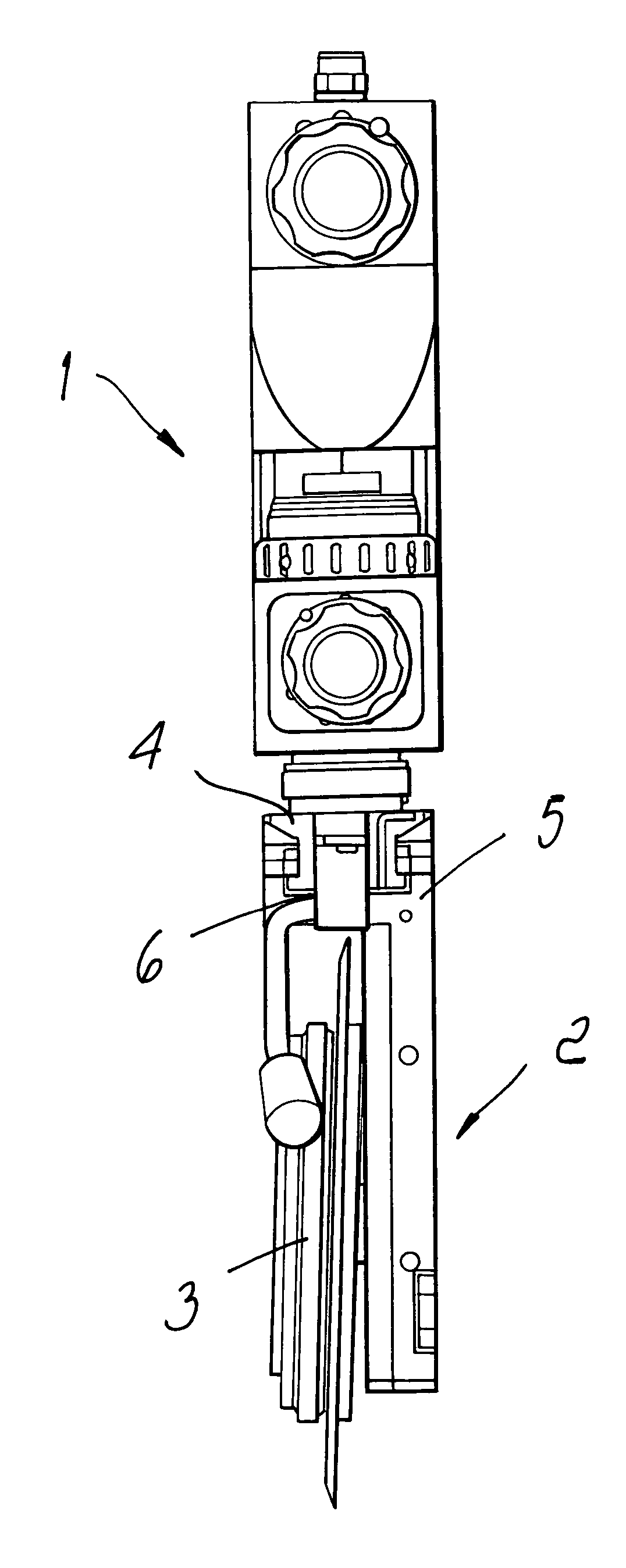
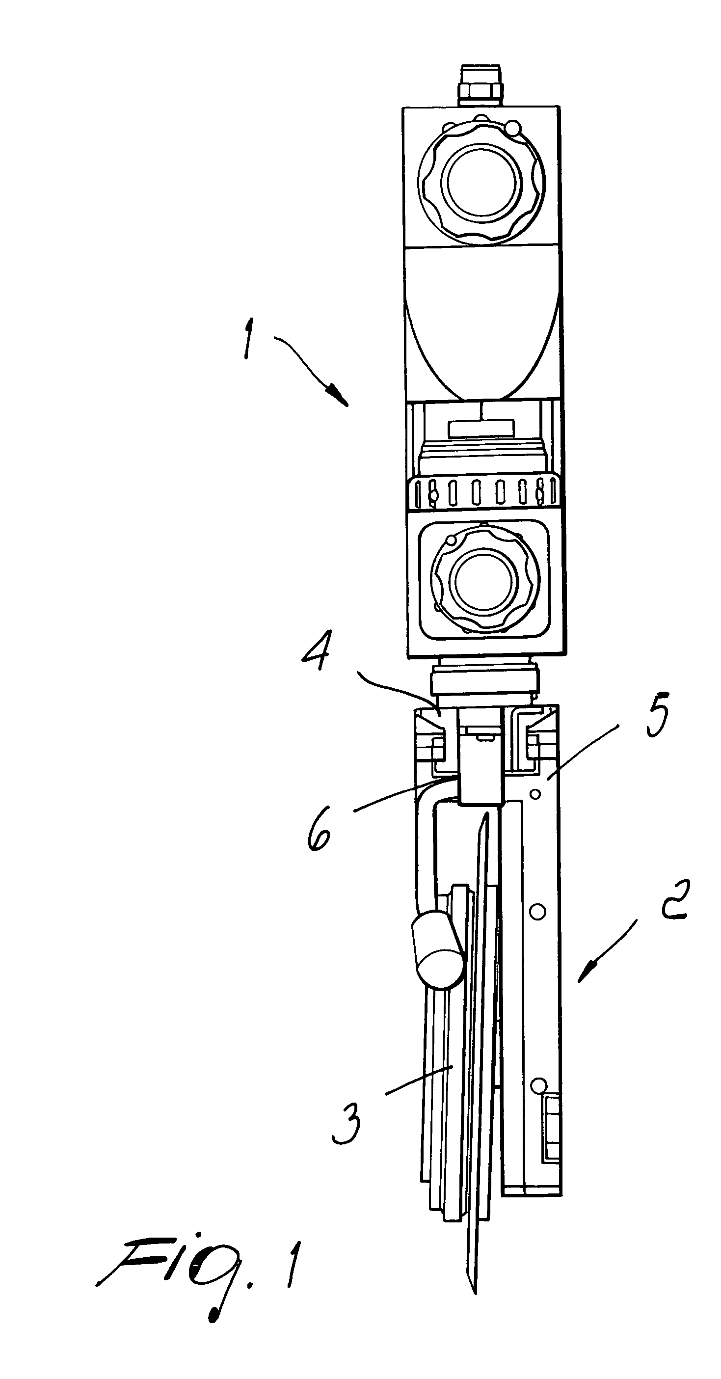
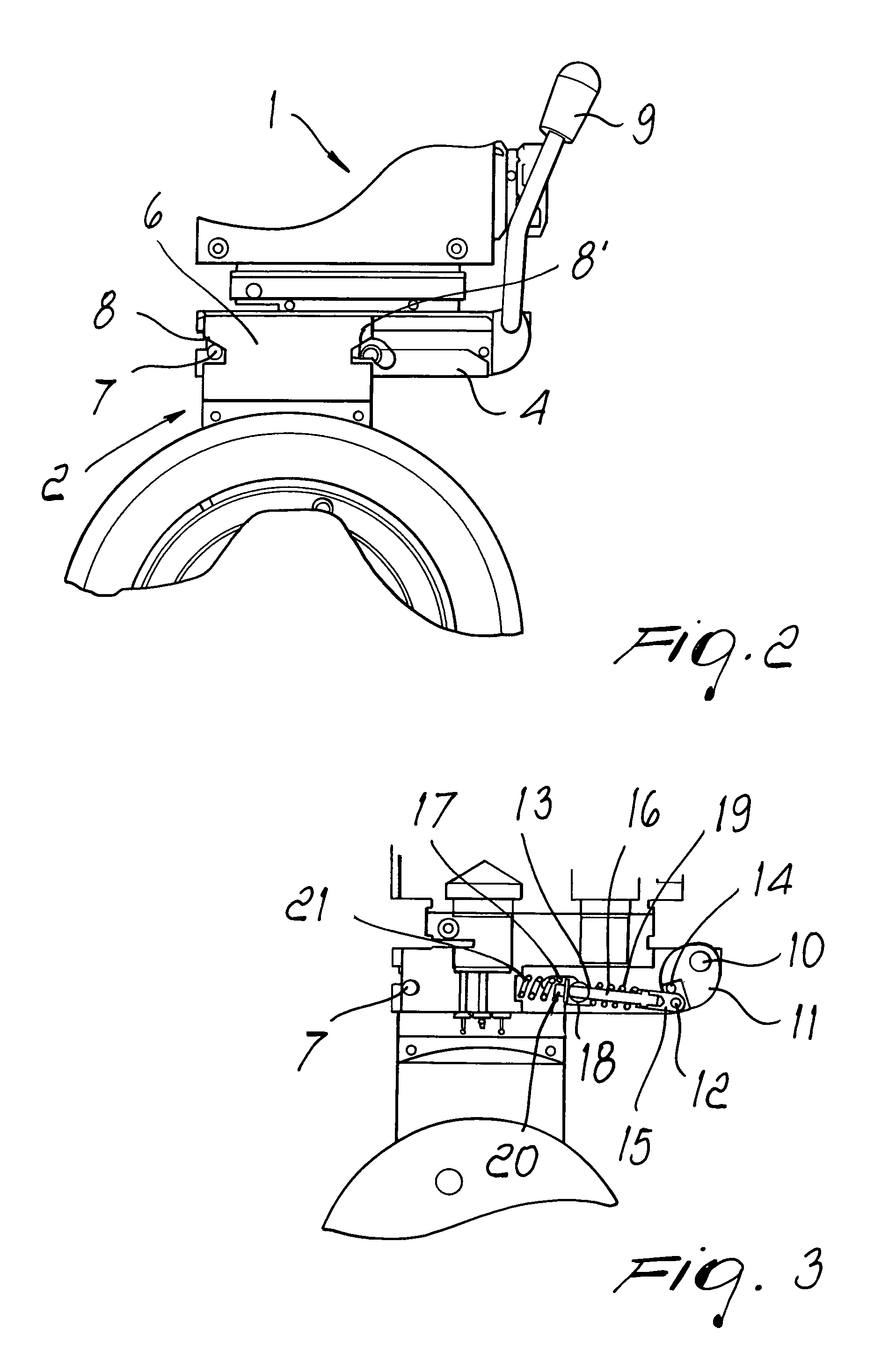
[0025]FIG. 1 illustrates a cutter holder, in which it is possible to distinguish the body of the cutter holder 1 and a removable cartridge 2 on which a cutter 3 is mounted. A dovetail slider 4, which is symmetrical on the right and left sides, is provided on the lower horizontal plane of the body of the cutter holder 1. The head portion 5 of the cartridge is provided with a slot 6, the profile of which is complementary to the profile of the dovetail slider 4, which allows the sliding engagement of the cartridge 2 on the body of the cutter holder 1, locking its degrees of freedom related to rotation about the vertical axis and translational motion along the vertical axis. With reference to FIGS. 2 and 3, on the side walls of the slider 4 there are symmetrically arranged stop pins 7, which are designed to stop the sliding of the slot 6 on the slider 4 in the point where the body of the cutter holder and the cartridge are mutually positioned correctly. For this purpose, the vertical wa...


PUM

PropertyMeasurementUnit
degrees of freedomaaaaaaaaaa
symmetryaaaaaaaaaa

Abstract

A system for engaging and locking the cartridge on the body of a cutter holder adapted to equip machines for the industrial cutting of flexible laminates, comprising a slider with a dovetail profile on the lower portion of the cutter holder body, the head portion of the cartridge being provided with a slot with a profile complementary to the profile of the slider for engagement of the cartridge on the cutter holder body, elements for locking the cartridge on the cutter holder body, and a lever for actuating locking elements, which comprise at least one movable element, which applies a symmetrical force with an upward traction component on both sides of the complementary profile of the slot.

Description

[0001]The present invention relates to a cutter holder adapted to equip machines for the industrial cutting of flexible laminates, and discloses a system for coupling the cartridge of the cutter to the cutter holder body.[0002]More specifically, the invention relates to a mechanism which is integrated in the body of the cutter holder and allows the engagement and locking of the cartridge on the body of the cutter holder, and to the corresponding means provided on the cartridge which cooperate with such mechanism.BACKGROUND OF THE INVENTION[0003]Modern systems for industrial cutting comprise several motorized cutting systems, each of which has a plurality of cutters arranged side-by-side and actuated simultaneously by devices which can have an electromagnetic, pneumatic or other operating principle and operate continuously even for three eight-hour shifts, seven days a week, as in the case of paper industries. Currently, scissor-type or pressure-type devices are mostly used to cut la...

Claims


Application Information

Patent Timeline
Patent Type & Authority Patents(United States)
IPC IPC(8): B23D19/00
CPCB26D7/2635B26D7/2621Y10T83/7876Y10T83/9481Y10T83/7747Y10T83/9457Y10T83/9461
Inventor ZANNINI, GUIDO
Owner ZINCOMETAL
Why Eureka
Try Eureka