Wire holder with single step installation into T-shaped hole in support substrate

a technology of wire holder and support substrate, which is applied in the direction of machine supports, other domestic objects, mechanical apparatus, etc., can solve the problem of unfavorable rotation of the clamp in the round hol

Inactive Publication Date: 2009-04-28
SONY CORP +1
View PDF18 Cites 88 Cited by
  • Summary
  • Abstract
  • Description
  • Claims
  • Application Information

AI Technical Summary

Benefits of technology

[0005]A method includes engaging one or more wires with a wire holder, and using one and only one install...

Problems solved by technology

A round hole can be used to enable a wire clamp that has an engagement post to be installed in the hole using...

Method used


Image

  • Wire holder with single step installation into T-shaped hole in support substrate
  • Wire holder with single step installation into T-shaped hole in support substrate
  • Wire holder with single step installation into T-shaped hole in support substrate

Examples


Embodiment Construction

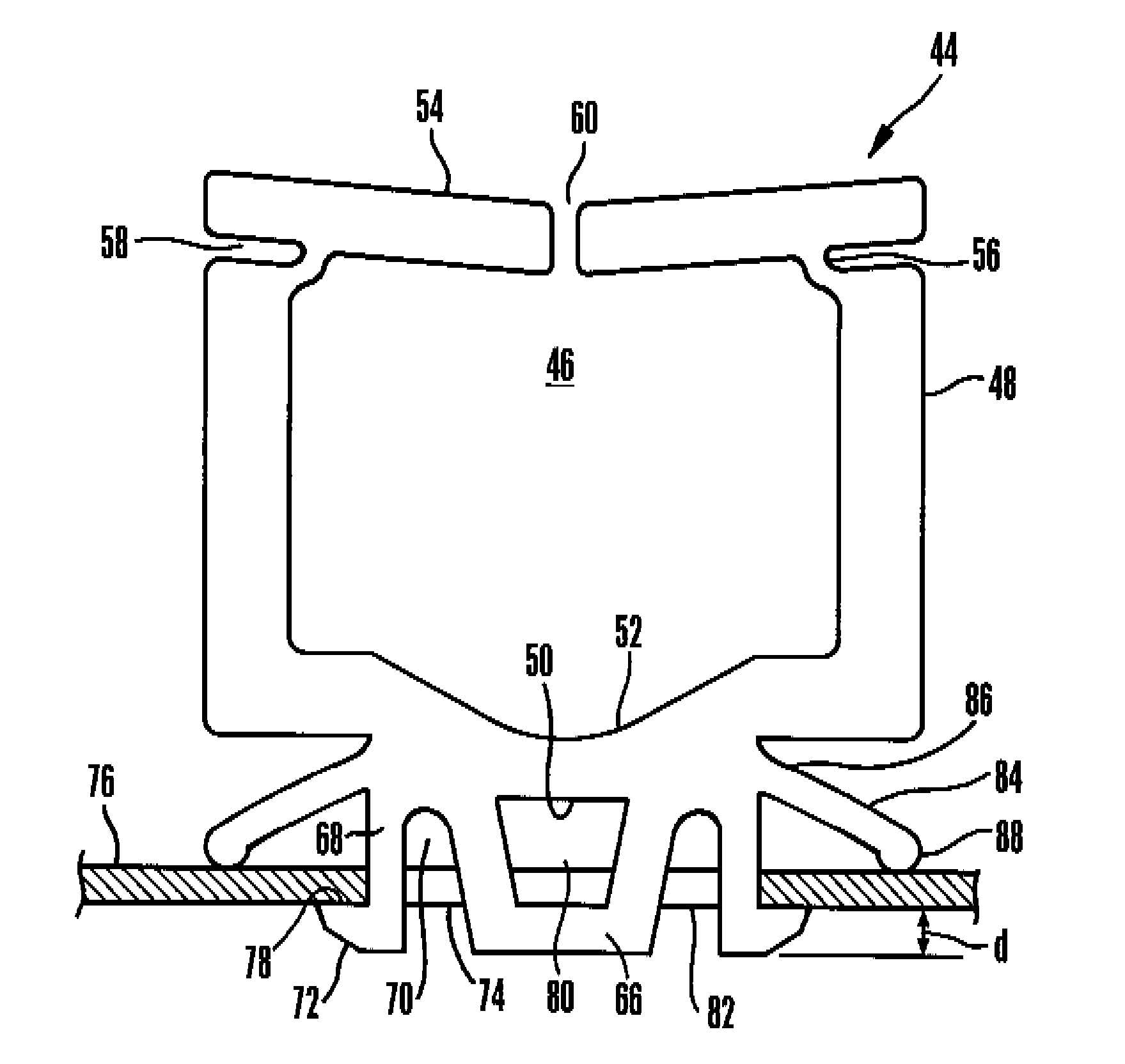
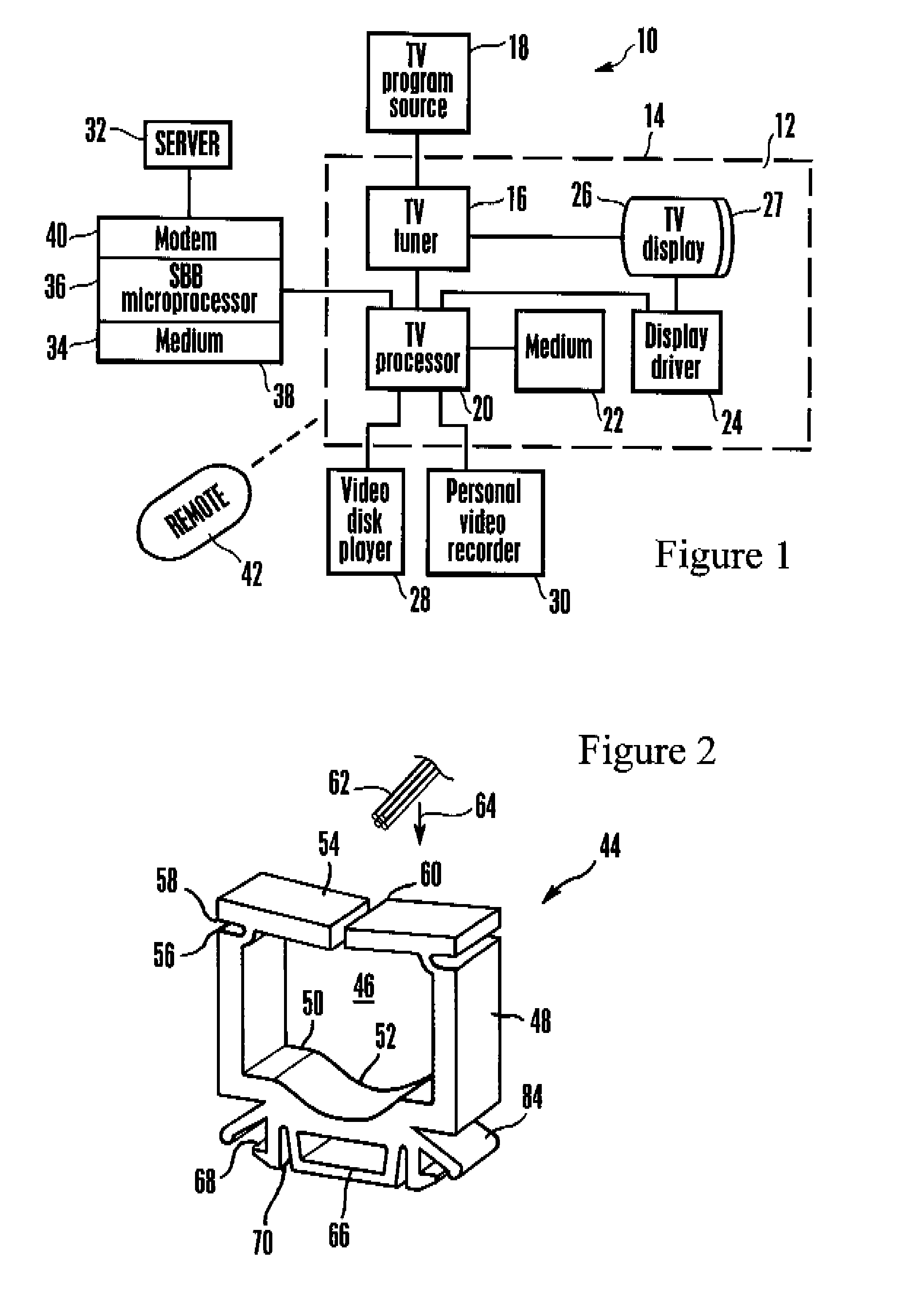
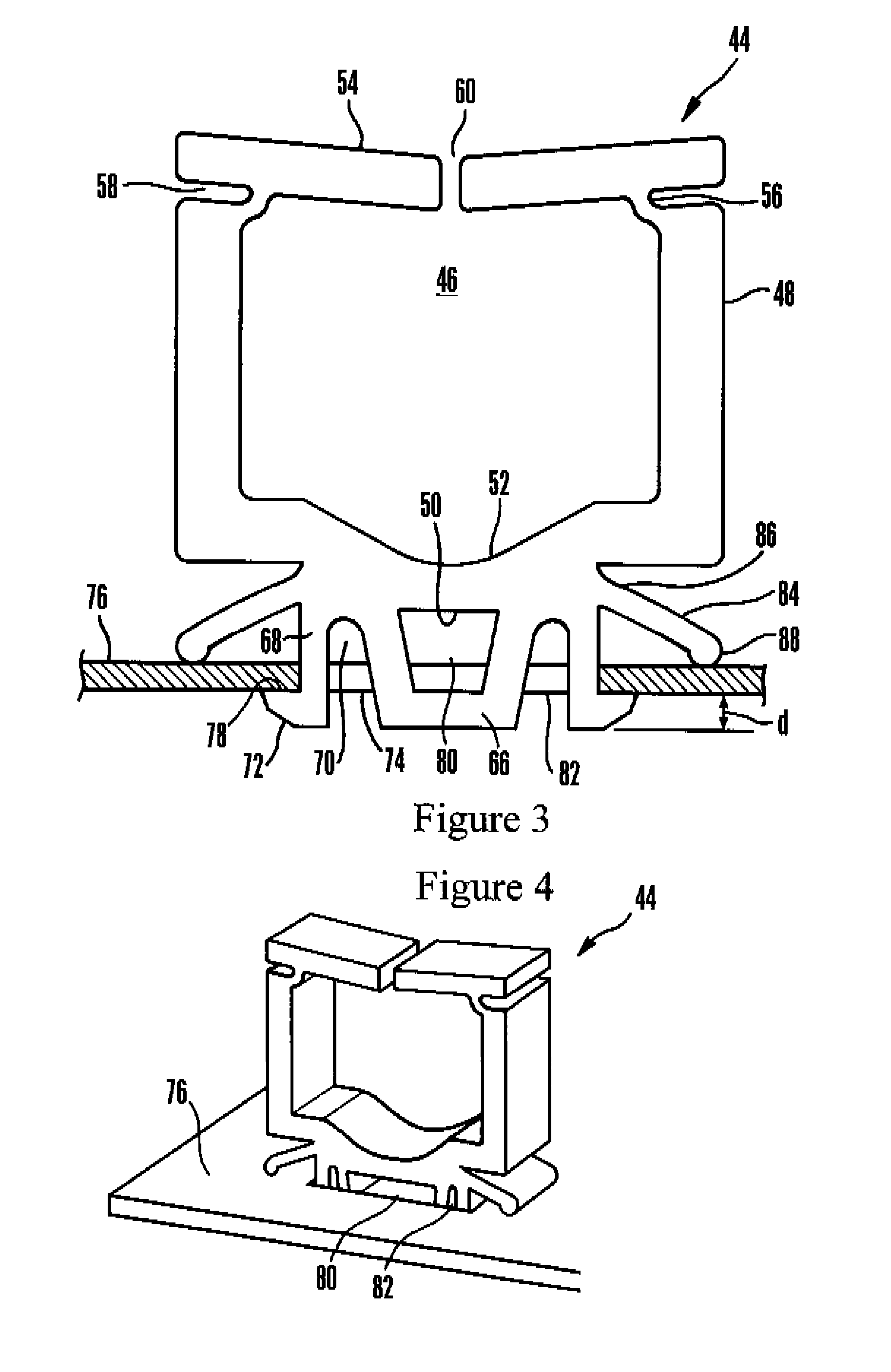
[0013]It is to be understood that while for ease of disclosure relative terms of direction such as “upper”, “lower”, “top”, “bottom”, etc. are used, these terms are not limiting. For example, the below-described wire holder might be engaged from below a substrate instead of from above it as shown in the drawings, i.e., it might be positioned upside-down from the orientation shown in the drawings.

[0014]Referring initially to FIG. 1, a system is shown, generally designated 10, which includes a television 12 defining a TV chassis 14 and receiving, through a TV tuner 16 from a cable or satellite or other source or sources 18 audio video TV programming. The tuner 16 may be contained in the set box described below. The system 10 is a non-limiting example of a system employing a substrate with which the below-described wire holder can be engaged.

[0015]The TV 12 typically includes a TV processor 20 accessing a tangible computer readable medium 22. The tangible computer readable medium 22 ma...


PUM


Abstract

A new wire holder design. The holder is installed into a T-shaped or L-shaped hole in substrate such as a sheet metal, printed wiring board, etc. using only a single installation motion. The holder holds wires in place. Because it requires only a single installation motion the holder is easily installed and furthermore cannot rotate once installed. The holder protrudes only about a millimeter below the substrate.

Description

FIELD OF THE INVENTION[0001]The present invention relates generally to wire holders that requires only a single installation motion to engage with a non-round hole such as a T-shaped hole in a substrate such as a TV circuit board.BACKGROUND OF THE INVENTION[0002]To hold wires on substrates such as sheet metal surfaces and printed wiring boards (PWB) in electrical components such as TVs, wire clamps can be used. The wires typically are engaged with the clamp and then the clamp is advanced into a hole in the substrate.[0003]As understood herein, in large-scale manufacturing it is desirable to minimize the number of movements that must accompany engaging the clamp with the substrate. A round hole can be used to enable a wire clamp that has an engagement post to be installed in the hole using a single downward pushing movement, but as understood herein such clamps can undesirably rotate in the round holes.[0004]To prevent clamp rotation after installation, non-round holes such as T-shap...

Claims


Application Information

Patent Timeline
IPC IPC(8): F16B15/00
CPCF16B5/0685F16L3/13F16L3/24F16L3/243H02G3/32
Inventor BARRY, KEITHEBBELING, DANIELKUBOTA, EUGENEMCCRAY, DENNISNAITO, RYOJISANCHEZ, MARIO
Owner SONY CORP
Why Eureka
Try Eureka