Directional interpolation method and device for increasing resolution of an image

a directional interpolation and image technology, applied in the field of image processing, can solve the problems of image discontinuity, image decision mistake is relatively increased, image is not natural, etc., and achieve the effect of increasing the resolution of the imag

Inactive Publication Date: 2009-05-12
SUNPLUS TECH CO LTD
View PDF8 Cites 4 Cited by
  • Summary
  • Abstract
  • Description
  • Claims
  • Application Information

AI Technical Summary

Benefits of technology

[0008]The object of the present invention is to provide a directional interpolation method and device for increasing resolution of an image, which can avoid the prior decision mistake, blur and discontinuousness of an image.

Problems solved by technology

Upon current TV broadcasting technology, odd and even display fields are alternately broadcasted due to limited bandwidth.
Such a broadcasting method may lose even or odd lines of an image in every display field at the vertical direction, and thus a typical TV only displays odd or even lines of the image in scanning and displaying.
However, when it is applied to an image pixel with smoother gradient or thin slashes, the interpolated images may cause decision mistakes due to insufficient image messages, and accordingly the image with thin slashes is shown in zigzag and blur.
However, when the reference image distance is increased, a probability of image decision mistake is relatively increased and thus an unnatural image is generated.
However, such a way mostly uses vertical interpolation for a complicated image and thus the image shows discontinuousness.

Method used


Image

  • Directional interpolation method and device for increasing resolution of an image
  • Directional interpolation method and device for increasing resolution of an image
  • Directional interpolation method and device for increasing resolution of an image

Examples


Embodiment Construction

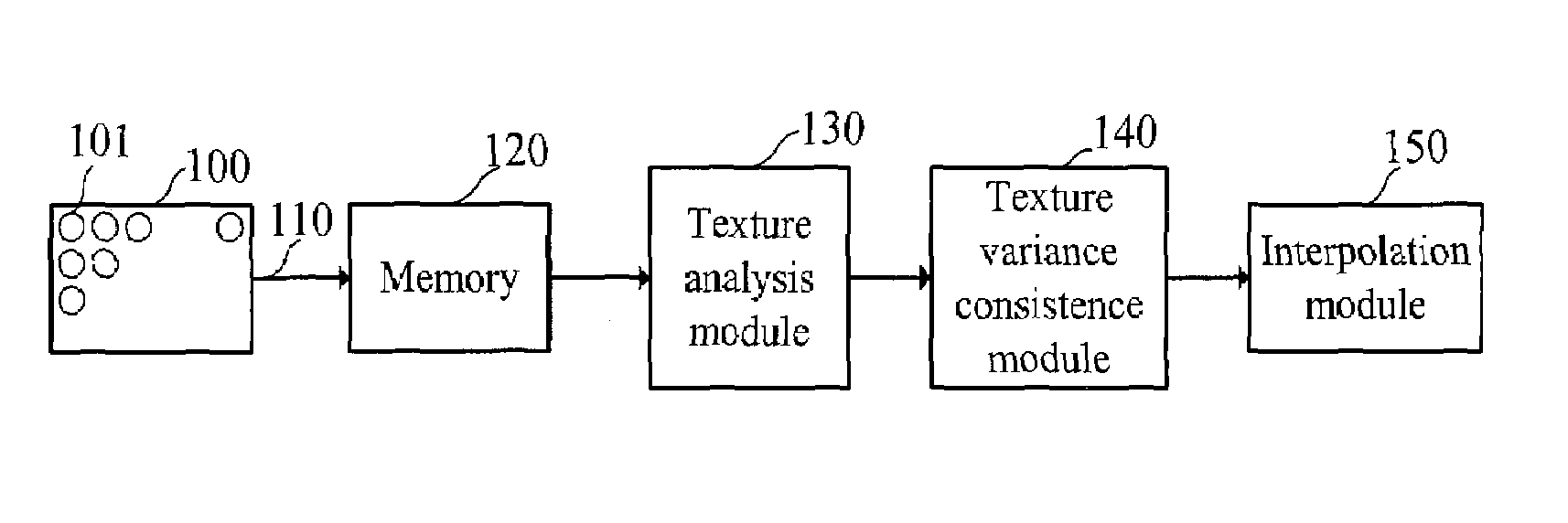
[0020]FIG. 1 is a block diagram of a directional interpolation device for increasing resolution of an image in accordance with the invention. As shown, the image 100 processed consists of pixels 101 arranged in rows and columns. The device adds a plurality of pixels to increase resolution of the image. Any of the pixels added is located on a position in the image 100. The device includes an input terminal 110, a memory 120, a texture analysis module 130, a texture variance consistence module 140 and an interpolation module 150.

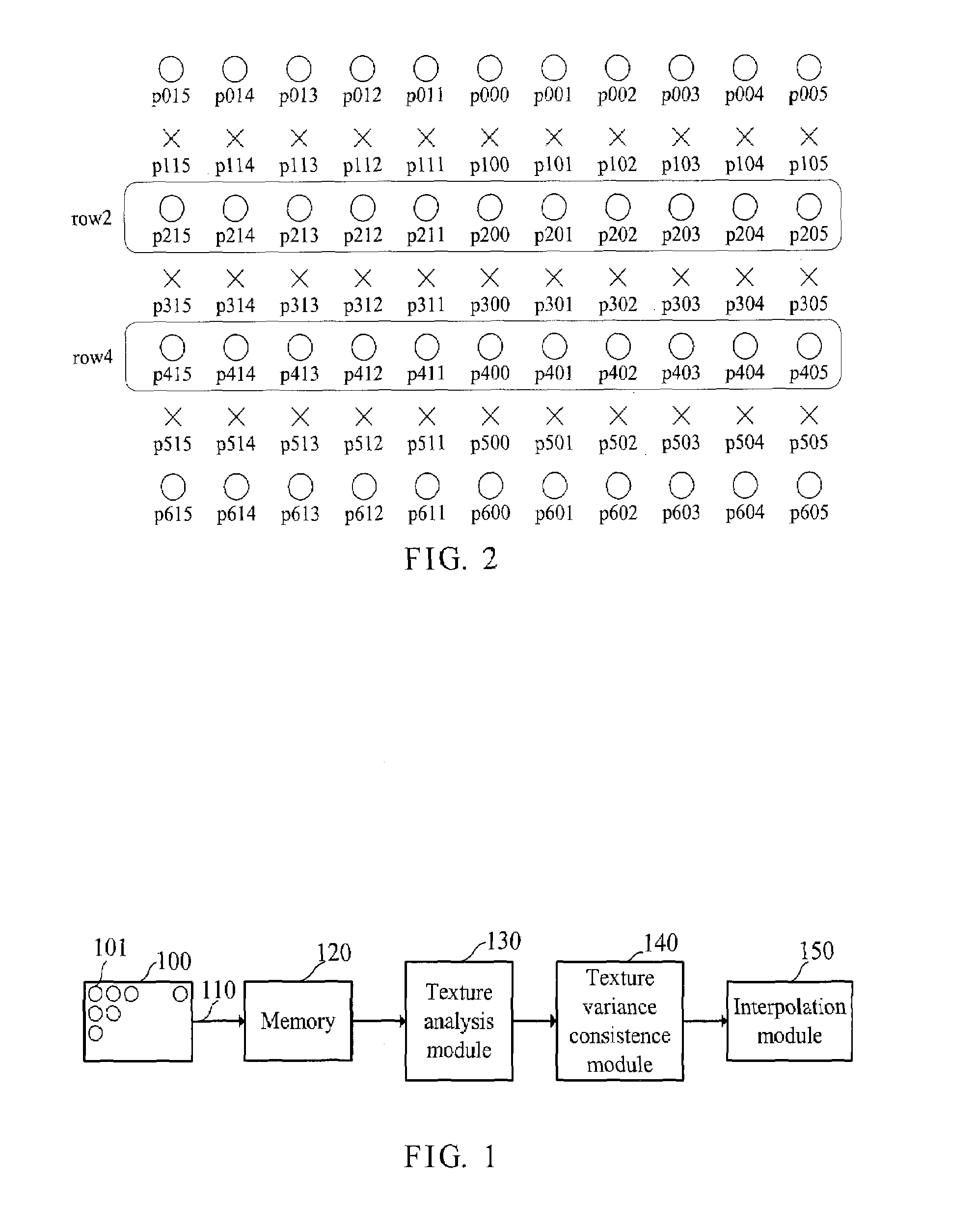
[0021]As shown in FIG. 1, the input terminal 110 receives signals representing the pixels 101 of the image 100. The memory 120 is connected to the input terminal 110 in order to store the pixels 101 of the image 100 in row direction. FIG. 2 shows partial pixels 101 of the image 100. As shown, circles represent original pixels of the image 100 and Xs represent pixels interpolated in the image 100. In this case, pixel p300 is given as an example to following ope...


PUM


Abstract

A directional interpolation method and device for increasing resolution of an image is disclosed. The device includes an input terminal, a memory, a texture analysis module, a texture variance consistence module and an interpolation module. The input terminal receives signals representing the pixels of the image. The memory stores the pixels in row direction. The texture analysis module obtains a monotone variation area by taking the position as a center. The texture variance consistence module computes all directional texture variances in a closest upper and a closest lower rows of pixels within the monotone variation area in the case of taking the position as a center and accordingly finds two pixels having texture variance consistence. The interpolation module finds a value of pixel to be interpolated to the position through a median filter in accordance with the two pixels and their neighbor pixels.

Description

BACKGROUND OF THE INVENTION[0001]1. Field of the Invention[0002]The present invention relates to the technical field of image processing and, more particularly, to a directional interpolation method for increasing resolution of an image.[0003]2. Description of Related Art[0004]Upon current TV broadcasting technology, odd and even display fields are alternately broadcasted due to limited bandwidth. Such a broadcasting method may lose even or odd lines of an image in every display field at the vertical direction, and thus a typical TV only displays odd or even lines of the image in scanning and displaying. However, new generation display systems such as liquid crystal displays (LCDs) have higher vertical resolution and thus obtain required high-resolution TV images by interpolation in vertical direction.[0005]U.S. Pat. No. 5,001,563 granted to Doyle, et al. for a “Method of and circuit for processing a picture signal” discloses a method for processing a picture signal to interpolate a...

Claims


Application Information

Patent Timeline
Patent Type & Authority Patents(United States)
IPC IPC(8): G06K9/32G06K9/36G06T3/40H04N5/00
CPCG06T3/4007
Inventor LU, ZHI-MINGLIN, KUN-WEI
Owner SUNPLUS TECH CO LTD
Why Eureka
Try Eureka