Technique to verify underground targets utilizing virtual reality imaging and controlled excavation

a virtual reality imaging and controlled excavation technology, applied in the direction of survey, directional drilling, borehole/well accessories, etc., can solve the problem of relative poor resolution

Inactive Publication Date: 2015-08-13
THOMPSON MICHAEL C
View PDF13 Cites 56 Cited by
  • Summary
  • Abstract
  • Description
  • Claims
  • Application Information

AI Technical Summary

Benefits of technology

[0020]In a further embodiment, a method of locating and verifying a position of an underground target includes excavating a vertical access borehole at initial coordinates representing a surface point positioned above the underground target. If the vertical access borehole engages the underground target, then the three-dimensional position of the underground target is verified. If the vertical access borehole does not engage the underground target, then a lateral sensor is lowered into the vertical access borehole to locate and determine three-dimensional coordinates of the underground target. A second borehole is then excavated from a second surface point and is directed into engagement with the underground target to its position. Preferably, a virtual reality display is used to show both the determined three-dimensional coordinates of the underground target as well as the real-time position of the second borehole to help guide a probe cutting head forming the second borehole to the underground target.

Problems solved by technology

In one embodiment, data acquisition begins with a ground surface low frequency GPR scan which locates a target but with relatively poor resolution.

Method used


Image

  • Technique to verify underground targets utilizing virtual reality imaging and controlled excavation
  • Technique to verify underground targets utilizing virtual reality imaging and controlled excavation
  • Technique to verify underground targets utilizing virtual reality imaging and controlled excavation

Examples


Embodiment Construction

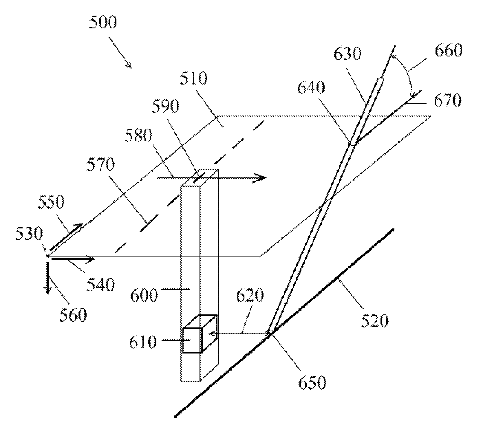
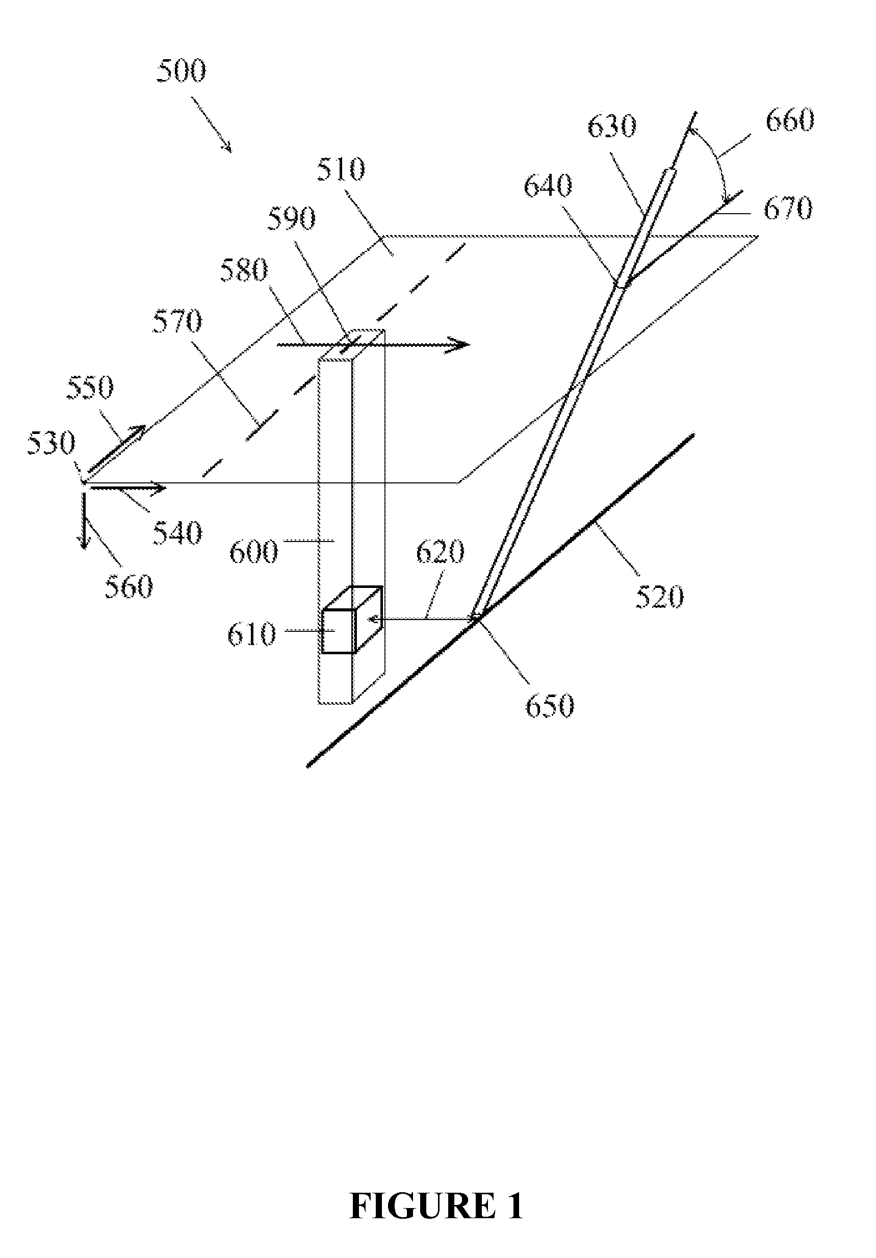
[0029]FIG. 1 illustrates a field excavation site (500) in an isometric view. A ground surface plane (510) is located above a buried utility target (520). This particular target (520) is linear, however any shape target may be located using this method. The target may also be a virtual-only target. A base point (530) is at a known location including coordinates used in the Global Positioning System (GPS). From the base point (530), the coordinates of any point on the surface plane (510) can be determined by horizontal distances in the x axis (540) and y axis (550) from any point to the base point (530). Vertical coordinates are defined by the z axis (560).

[0030]In this embodiment, a surface marking (570) is placed above the target (520) by locating equipment such as Ground Penetrating Radar (“GPR”) which can also display a depth of the target (520). The accuracy of such location varies and cannot typically be relied upon for a precise location of the target (520). Visual verification...


PUM


Abstract

A system and method for locating and verifying a position of an underground target utilizes a virtual reality display to guide a cutting probe to the target. Initial coordinates of the target may be obtained from prior survey data and a vertical access borehole is excavated at the initial coordinates in a first attempt to verify the target position. If the target it not encountered at the initial coordinates, a lateral sensor is positioned within the vertical access borehole to determine three-dimensional coordinates of the target. A second borehole is then excavated by a cutting head that is guided to the three-dimensional target coordinates with the assistance of a virtual reality display that shows both the target coordinates and a real time position of the cutting head. A down-hole camera or other sensor positioned within the second borehole may verify the presence or condition of the target.

Description

FIELD OF THE INVENTION[0001]The present disclosure generally relates to locating and verifying the position of underground targets utilizing real time virtual reality imaging and data acquisition including Ground Penetrating Radar (GPR), where controlled drilling apparatuses are used to excavate material, such as dirt, rock, or sand. More particularly, the disclosure relates to providing a visual display from 3D modeling in virtual space in addition to excavating stealth boreholes by monitoring, controlling, and recording drilling process information, including the cutting head location within the formation. Drilling process information includes the temperature and pressure of drilling fluids, including fluids and soil composition within an excavation chamber of a drilling apparatus.BACKGROUND OF THE INVENTION[0002]Location and verification of utilities and other underground targets begins with the location and recording of the target position on the ground surface above the buried ...

Claims


Application Information

Patent Timeline
Patent Type & Authority Applications(United States)
IPC IPC(8): E21B7/04
CPCE21B7/04E21B7/027E21B7/18E21B21/08G01S13/86G01S13/885G01S13/89G01V3/30
Inventor THOMPSON, MICHAEL C.
Owner THOMPSON MICHAEL C
Why Eureka
Try Eureka