Flush syringe having anti-reflux features

a technology of syringe and syringe, which is applied in the direction of medical syringe, infusion device, intravenous device, etc., can solve the problems not as efficient as those dedicated to catheter maintenance, and on the rise of reflux of blood into the catheter, so as to reduce or eliminate reflux. the effect of blood reflux

Active Publication Date: 2009-05-19
BECTON DICKINSON & CO
View PDF21 Cites 20 Cited by
  • Summary
  • Abstract
  • Description
  • Claims
  • Application Information

AI Technical Summary

Benefits of technology

[0007]The present invention is directed to a syringe assembly for use in flush applications. The syringe assembly reduces or eliminates reflux of blood into the catheter by providing a proximally facing annular boss on the inside surface of the distal wall of the syringe barrel. The boss projects into the fluid containing chamber of the barrel and surrounds the passageway in the barrel tip through which flush solution is discharged. The annular boss is positioned so that it contacts the distal surface of the stopper and seals the passageway before other portions of the inside surface of the distal wall of the barrel surrounding the boss contact the stopper. Further compression of the stopper will be independent of this seal so that reflux is reduced or eliminated.

Problems solved by technology

This is undesirable, since it can cause blood to enter the catheter at the catheter distal end (reflux).
Problems with reflux of blood into the catheter are on the rise because IV lines are now being flushed by a wide variety of health care workers not just those dedicated to catheter maintenance.
These other health care workers, as a result of having many other aspects of patient care to be responsible for and who spend much less time flushing IV lines, are not as efficient as those dedicated to catheter maintenance.
For example, prematurely releasing the compressive force on the stopper, which may cause reflux of blood into the catheter.

Method used


Image

  • Flush syringe having anti-reflux features
  • Flush syringe having anti-reflux features
  • Flush syringe having anti-reflux features

Examples


Embodiment Construction

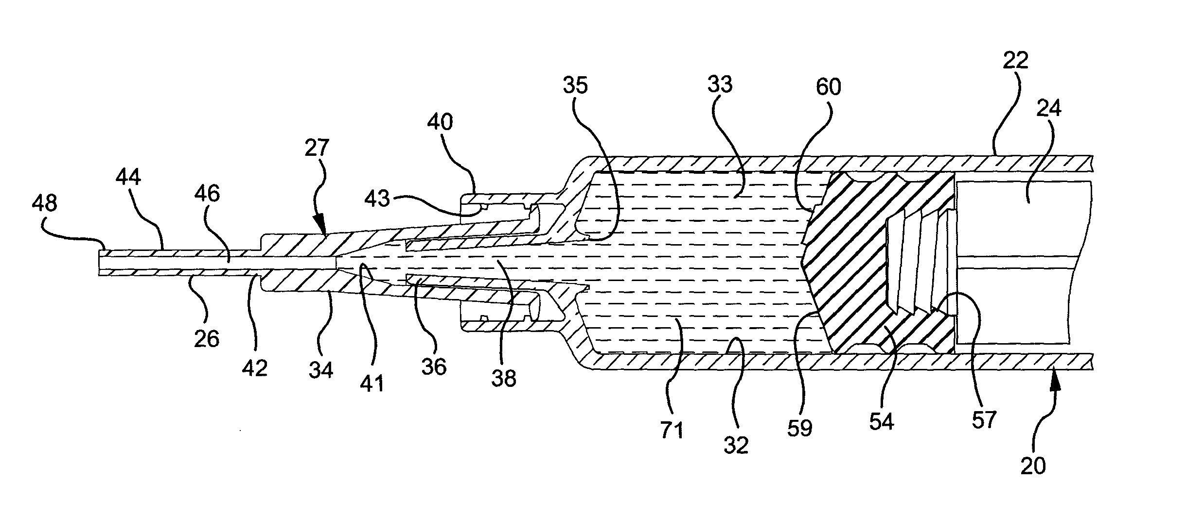
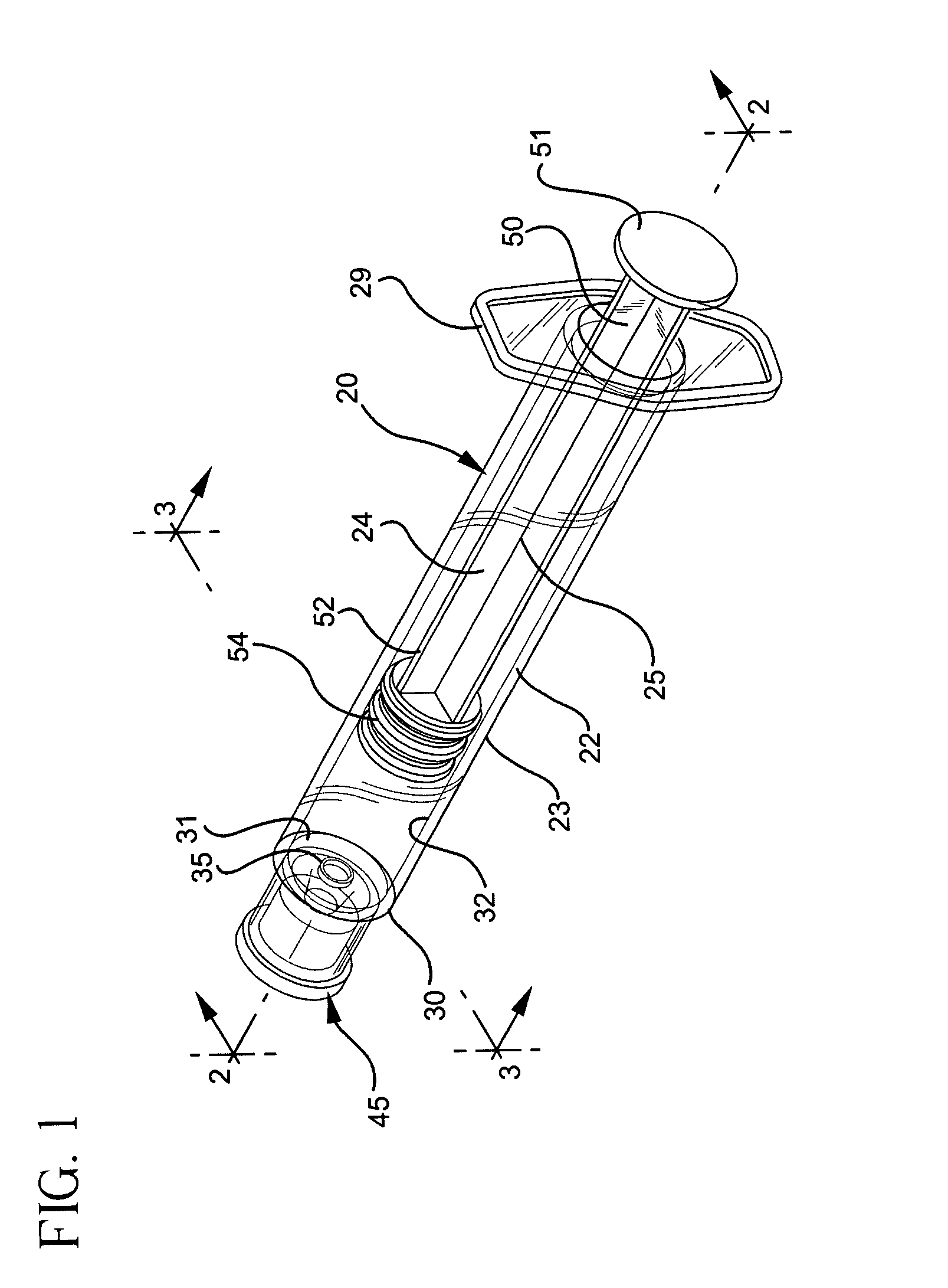
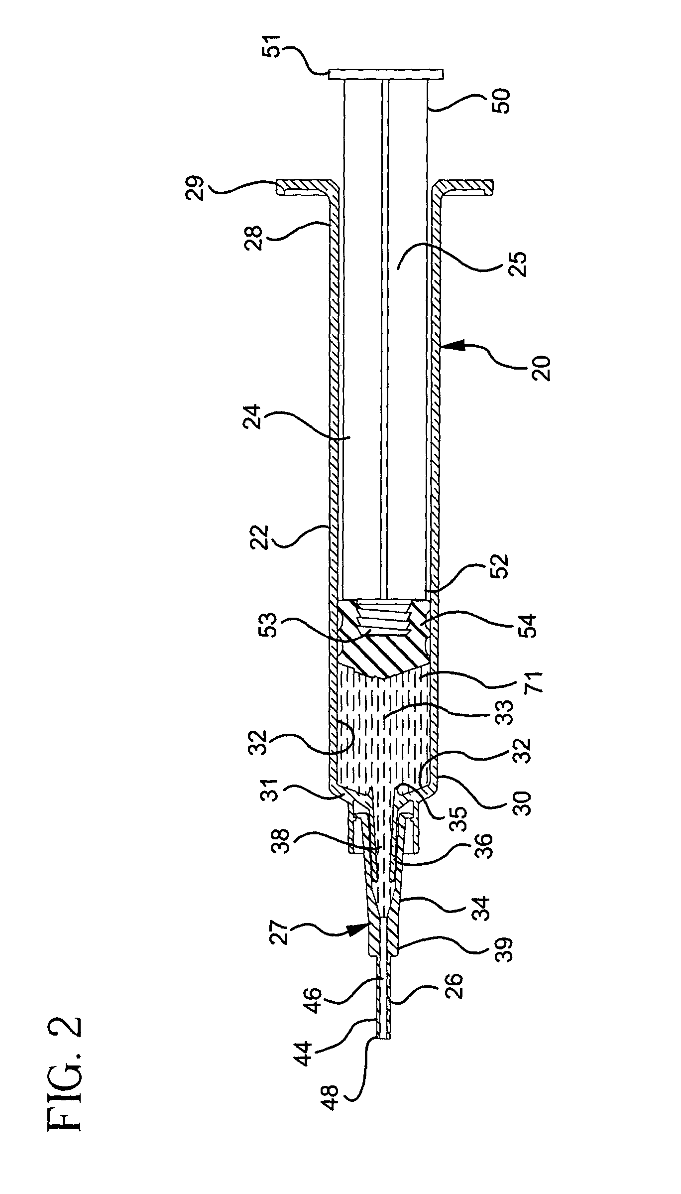
[0022]Referring to FIGS. 1-6, a syringe 20 according to the present invention generally comprises a barrel 22, and a plunger 24. The barrel 22 has a generally cylindrical side wall 23 including an open proximal end 28 having finger grips 29, a distal end 30 having a distal wall 31 and an inside surface 32 defining a chamber 33 for retaining fluid. The inside surface of the barrel at the distal wall is preferably conically shaped and includes a proximally facing annular boss 35. Distal end 30 further includes a tip 36 having a passageway 38 in fluid communication with the chamber. The distal end of barrel 22 preferably, but not necessarily includes a locking luer type collar 40 concentrically surrounding tip 36. The inside surface of the collar includes at least one thread 43. A cannula 26 includes a proximal end 42, a distal end 44 and a lumen 46 therethrough. The distal end may include a sharp tip or a blunt tip 48 as shown. The cannula may be connected directly to the tip of the s...


PUM


Abstract

An I.V. flush syringe assembly includes a barrel having an inside surface defining a chamber for retaining fluid, an open proximal end and a distal end including a distal wall with an elongate tip extending distally therefrom having a passageway therethrough in fluid communication with the chamber. A plunger having an elongate body portion and a stopper slidably positioned in fluid-tight engagement with the inside surface of the barrel is provided. Anti-reflux structure in said barrel is provided for controlling stopper deflection when fluid has been delivered from the chamber and the stopper is in contact with structure on the distal wall.

Description

BACKGROUND OF THE INVENTION[0001]The present invention relates to syringe assemblies and particularly to syringe assemblies for use in I.V. flush procedures.[0002]An I.V. catheter is a commonly used therapeutic device. Many patients, in accordance with their therapy, have an I.V. catheter connected to a vein ready for use in various procedures or in fluid communication with an I.V. system for infusing liquids and medication. Many I.V. sets have I.V. ports which are in fluid communication with a catheter and allow access for the purpose of injecting medication into the patient, and for use in flushing techniques to maintain catheter integrity. Healthcare facilities have flushing protocols which depend on the amount of time the catheter will remain in the patient and the type of catheter being used. For example, a peripherally inserted central catheter (PICC) is a long flexible catheter, which is typically inserted into the central venous system (optimally with the tip terminating in ...

Claims


Application Information

Patent Timeline
Patent Type & Authority Patents(United States)
IPC IPC(8): A61M5/315A61M5/14A61M5/31
CPCA61M5/31511A61M2005/1403A61M2005/3104A61M2005/31523A61M2005/3132A61M5/178A61M5/31
Inventor SCHILLER, ERICHOTTOVY, TRACY RAYALHEIDT, THOMAS A.DUTT, MITALI
Owner BECTON DICKINSON & CO
Why Eureka
Try Eureka