Electrical hose swivel connector

a technology of swivel connectors and hoses, which is applied in the direction of current collectors, electric and fluid couplings, electrical apparatus, etc., can solve the problems of inefficient use and difficulty of clippers

Inactive Publication Date: 2009-05-26
RASHKOVER IRWIN
View PDF11 Cites 26 Cited by
  • Summary
  • Abstract
  • Description
  • Claims
  • Application Information

AI Technical Summary

Problems solved by technology

As such, it is not uncommon in such systems for the vacuum hose and the power cord to frequently and undesirably twist and knot together making use of the clippers difficult and inefficient.

Method used


Image

  • Electrical hose swivel connector
  • Electrical hose swivel connector
  • Electrical hose swivel connector

Examples


Embodiment Construction

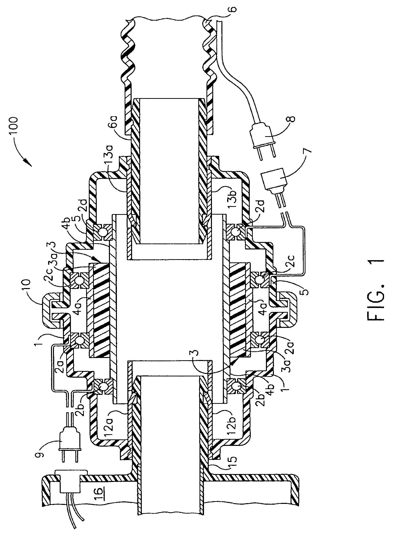
[0007]Referring now to FIG. 1, a non-twist linear contacts electrical hose swivel connector 100 is shown. The connector 100 generally comprises a first power transfer coupling 1, a connector body 3, and a second power transfer coupling 5. The first power transfer coupling 1 preferably comprises a body which encompasses a first metallic ring 2a and a second metallic ring 2b. Each ring 2a, 2b may be rigidly secured within the body of the first coupling 1 by way of a snap-fit between the ring and a corresponding groove within the body of the coupling 1, an adhesive, or any suitable means as known in the art. Also, the first power transfer coupling 1 preferably includes an electrical connector 9 for providing electrical communication between the rings 2a, 2b and the clipper 16. The second power transfer coupling 5 preferably comprises a body which encompasses a first metallic ring 2c and a second metallic ring 2d. Each ring 2c, 2d may be rigidly secured within the body of the second cou...


PUM


Abstract

An electrical hose swivel connector may be used to connect a vacuum hose to a hair clipping device. The hair clipping device may need power, which may be delivered from a power source and through a power cord. The power cord may be in electrical communication with this electrical hose swivel connector to deliver power to the hair clipping device. This electrical hose swivel connector can allow for easier use of the hair clipping device, which may be used with the vacuum hose without causing tangling, twisting, or knotting in the power cord.

Description

[0001]The present application claims priority benefit of U.S. Provisional Patent Application 60 / 848,977 filed Oct. 3, 2006 which is incorporated herein by reference in its entirety.TECHNICAL FIELD[0002]This invention relates to hair clipping devices having vacuum hoses and, more particularly, to a swivel connector for connecting a vacuum hose between a vacuum device and a hair clipper.BACKGROUND OF THE INVENTION[0003]Prior art hair clipping devices are commonly connected to a vacuum hose in addition to a required power source. Such prior art hair clipping devices are characterized by having a separate vacuum hose and a separate power cord which connects the clipper to the electrical power source. The usage of such hair clippers, particularly when being used to groom pets, requires constant motion and direction changes. As such, it is not uncommon in such systems for the vacuum hose and the power cord to frequently and undesirably twist and knot together making use of the clippers di...

Claims


Application Information

Patent Timeline
Patent Type & Authority Patents(United States)
IPC IPC(8): H01R39/00
CPCB26B19/44H01R39/643H01R13/005
Inventor RASHKOVER, IRWIN
Owner RASHKOVER IRWIN
Why Eureka
Try Eureka