Mounting assembly and installation

a technology for mounting assemblies and mounting brackets, which is applied in the direction of washstands, curtain suspension devices, lighting support devices, etc., can solve the problems of inconvenient use of anchors and toggle bolts, a hole which requires substantial repair of drywall, and a large hole in the drywall

a technology for mounting assemblies and mounting brackets, which is applied in the direction of washstands, curtain suspension devices, lighting support devices, etc., can solve the problems of inconvenient use of anchors and toggle bolts, a hole which requires substantial repair of drywall, and a large hole in the drywall

US7540458B2Inactive Publication Date: 2009-06-02A TOUCH OF CLASS

Image

  • Mounting assembly and installation
  • Mounting assembly and installation
  • Mounting assembly and installation

Examples


Embodiment Construction

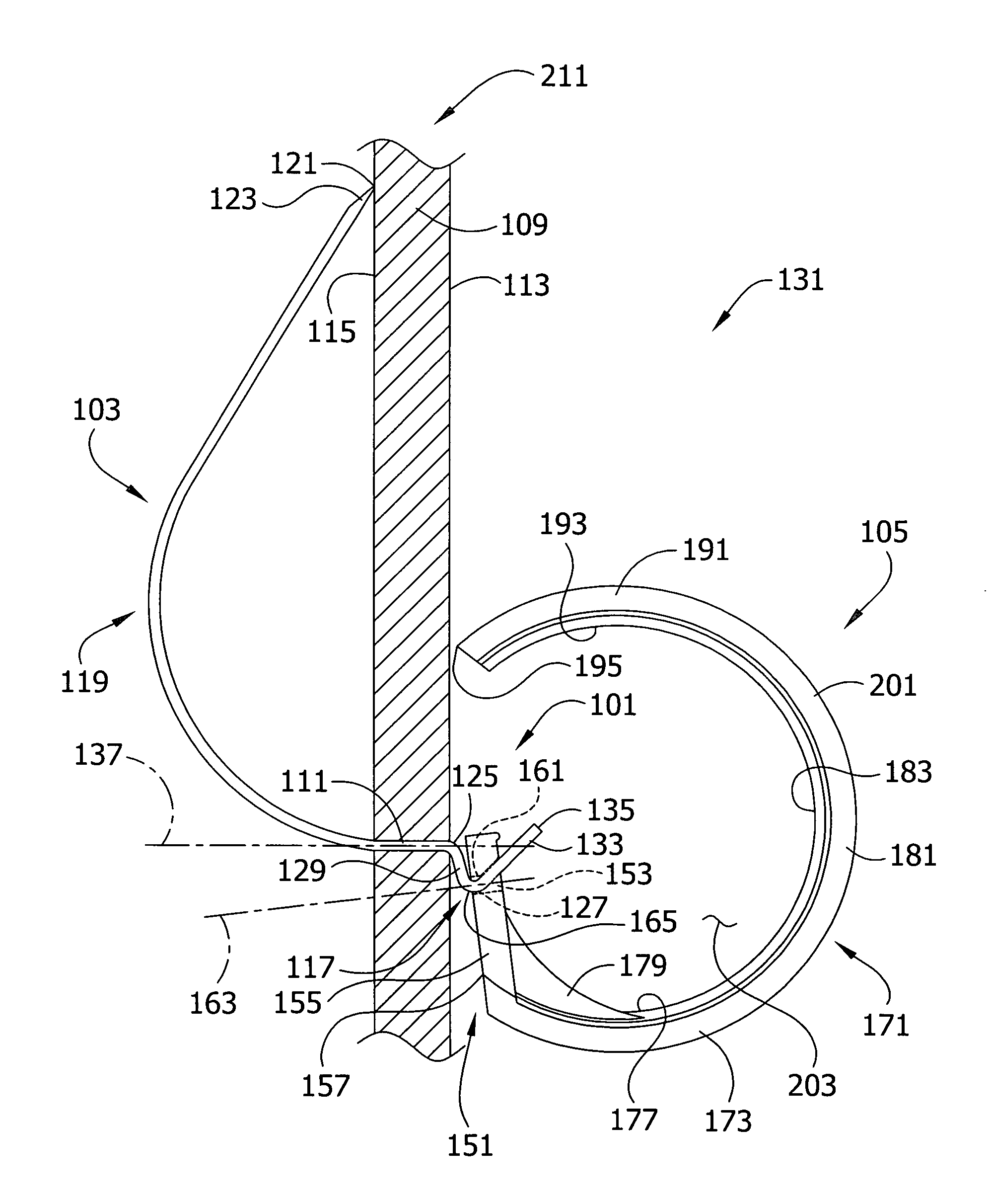
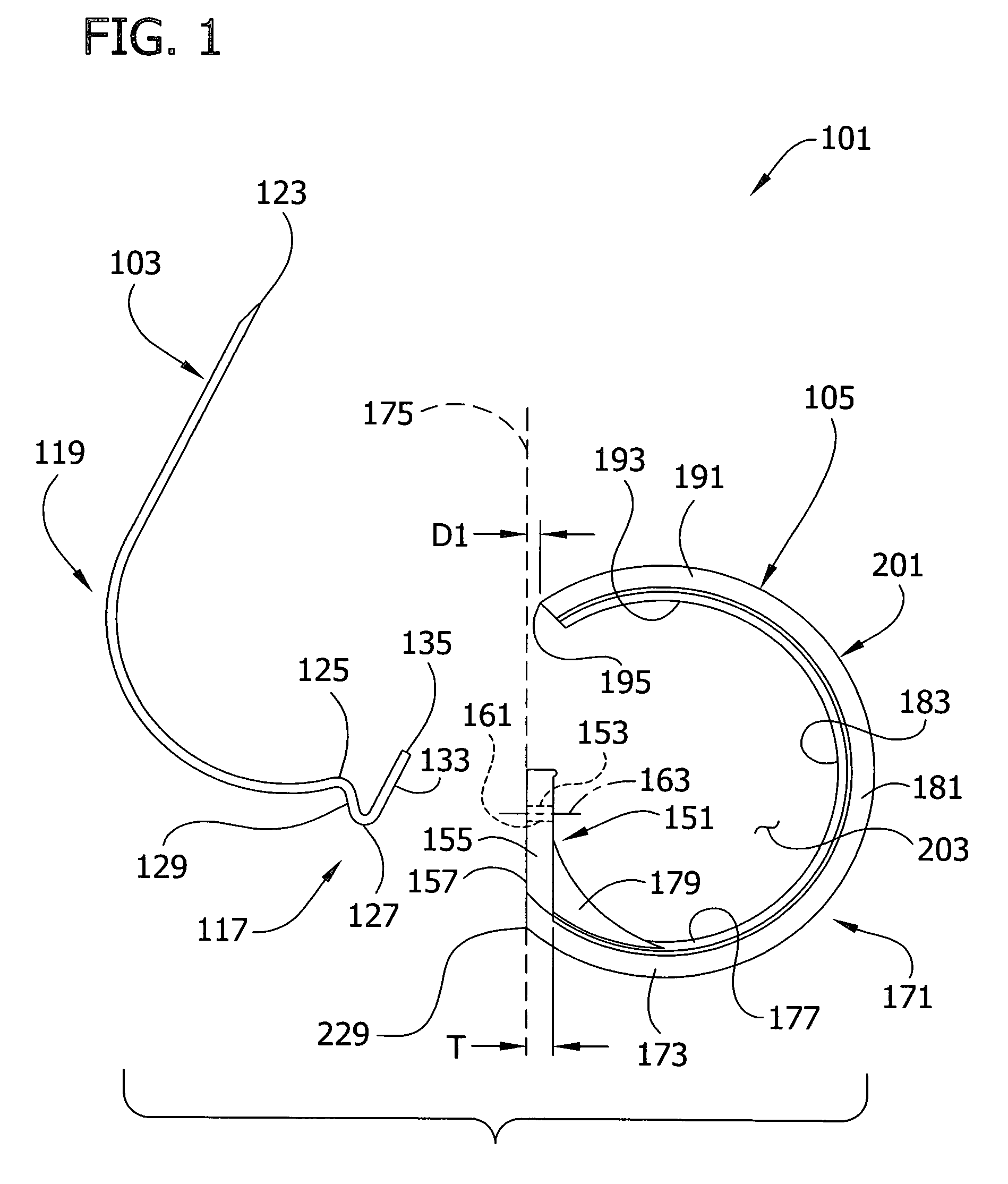
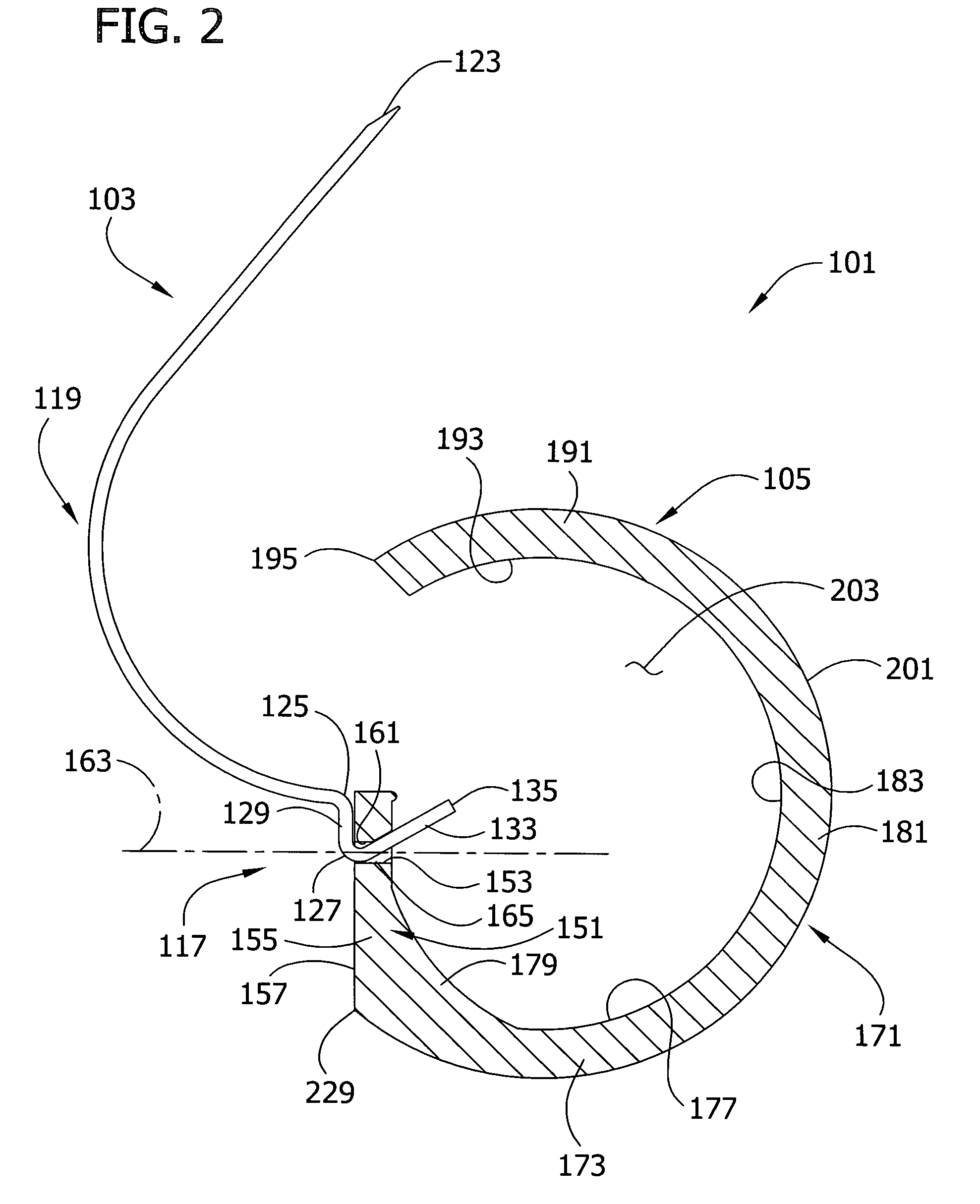
[0026]Referring to the drawings, initially to FIGS. 1 and 2, one embodiment of a mounting assembly of the present invention is generally designated 101. The mounting assembly comprises a wire hook 103 and an object holder 105. The wire hook 103 is adapted to be self-driven through the thickness of a wall or ceiling panel (e.g., a sheet of drywall). Broadly speaking, the wire hook 103 is configured to be received in an opening 111 in the panel 109 (e.g., an opening of its own making) extending from the front side 113 to the back side 115 so that only a relatively short hook portion 117 at one end of the wire hook protrudes from the front side, while a longer portion 119 of the wire hook at an opposite end thereof extends from the opening at the back side 115 to engage the back side of the panel at a location 121 spaced from the opening (FIG. 3). The object holder 105 can be hung on the hook portion 117 of the wire hook 103 to form a mounting installation 131 of the present invention....


PUM


Abstract

An mounting assembly for a wall or ceiling panel comprises a wire hook configured to be received in an opening extending through the panel from the front side to the back side thereof so that only a relatively short hook portion extends from the front side, while a relatively longer segment of the wire hook extends from the opening at the back side of the panel to engage the back side of the panel at a location spaced from the opening. The assembly also comprises an object holder for holding the object. The object holder has a mounting portion defining a bore for receiving the hook portion of the wire hook. The object holder has an arm extending from the mounting portion and defining a support surface for supporting the object. In one embodiment of the invention, the assembly is installed on a wall or ceiling panel.

Description

CROSS-REFERENCE TO RELATED APPLICATIONS[0001]This application claims the benefit of U.S. Provisional Application No. 60 / 676,696, filed Apr. 29, 2005, entitled MOUNTING FIXTURE FOR MOUNTING FLEXIBLE ITEMS ON DRYWALL, herein incorporated by reference.FIELD OF INVENTION[0002]This invention relates to devices for hanging or mounting items on walls or ceilings, especially relatively large items such as curtains, drapes, swags and the like.BACKGROUND[0003]The art is replete with devices far hanging items on drywall, many of which result in the punching, drilling or otherwise providing a relatively large hole into the drywall. When the device is removed from the drywall, there remains a hole which requires substantial repair to the drywall.[0004]For example, mounting fixtures for curtain rods and other large items often use wall anchors in which a plastic or metal sleeve is inserted into a pre-drilled hole through the drywall. The sleeve expands when a screw is screwed into the hole. The p...

Claims


Application Information

Patent Timeline
02 Jun 2009
Publication
US7540458B2
IPC
A47H1/16
CPC
F16B45/00; F16B45/012
Inventors
FORBES, CAROL S.