Power driven tilting inversion exerciser

a technology of tilting inversion exerciser and power drive, which is applied in the direction of stilts, chiropractic devices, physical therapy, etc., can solve the problems of not being operated by power driving apparatuses, parts or feet of users may not be solidly secured to the platform, and may have a good chance of disengagemen

Active Publication Date: 2009-06-09
TEETER ROGER C +1
View PDF14 Cites 22 Cited by
  • Summary
  • Abstract
  • Description
  • Claims
  • Application Information

AI Technical Summary

Benefits of technology

[0010]The other objective of the present invention is to provide a tilting inversion exerciser including a safety device for switching off the ankle holder or foot retaining device and for preventing the ankle holder or foot retaining device from being operated or actuated inadvertently, particularly when the tilting inversion exerciser is rotated or operated relative to the supporting stand by the user.
[0011]In accordance with one aspect of the invention, there is provided a tilting inversion exerciser comprising a supporting stand, a table rotatably supported on the supporting stand with a pivot axle for supporting a user on the table, a power actuating foot retaining device attached to the table for being powered and actuated to clamp and to retain ankle portions of the user to the table, and a safety device for switching off the foot retaining device to prevent the ankle portions of the user from being disengaged from the foot retaining device inadvertently when the table is operated by the user.

Problems solved by technology

However, the ankle portions or the feet of the user may not be solidly secured to the platform such that the ankle portions or the feet of the user may have a good chance to be disengaged from the platform particularly when the platform is inverted relative to the ground.
However, the locking device or ankle holder or foot retaining device is required to be operated manually, but may not be operated by power driving apparatuses.
It will be difficult for some of the users to bend over their bodies and to reach and to manually operate the locking device when the user has lain on the table of the inversion exercises.

Method used


Image

  • Power driven tilting inversion exerciser
  • Power driven tilting inversion exerciser
  • Power driven tilting inversion exerciser

Examples


Embodiment Construction

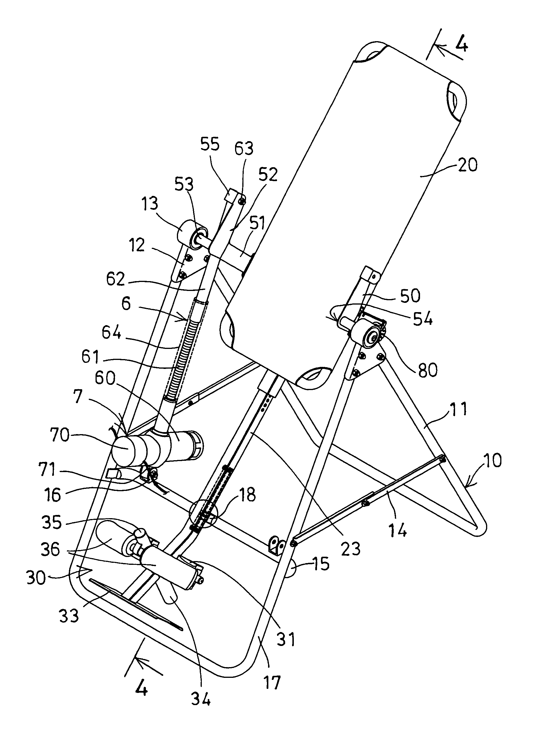
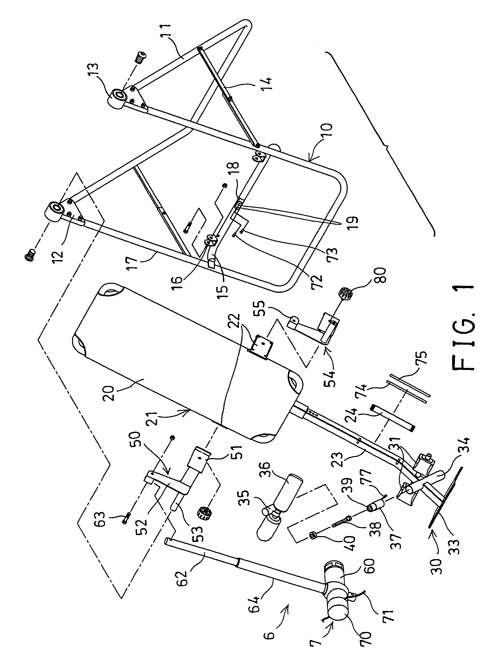
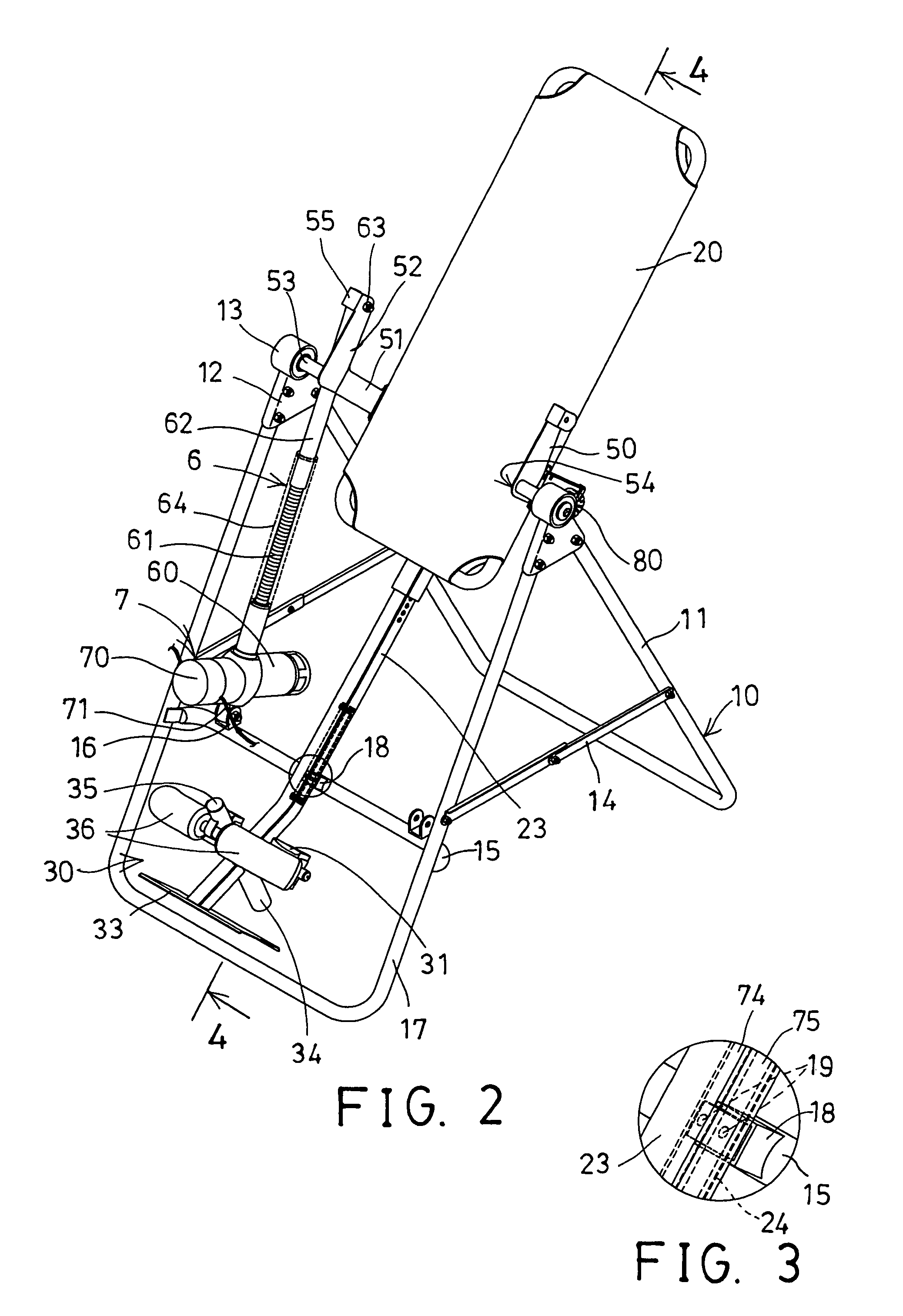
[0030]Referring to the drawings, and initially to FIGS. 1-4, a tilting inversion exerciser in accordance with the present invention comprises a lower supporting stand 10 for pivotally or rotatably supporting a base or table 20 thereon, and for supporting a user on the table 20, the lower supporting stand 10 includes such as two U-shaped frames 11 having upper ends pivotally coupled together with two apex members 12 so as to form a substantially inverted V-shaped structure. The lower supporting stand 10 includes a bearing support 13 disposed or attached to each of the apex members 12 for pivotally or rotatably supporting or coupling the supporting table 20.

[0031]The lower supporting stand 10 includes one or more, such as two foldable coupler 14 coupled between the frames 11 for allowing the frames 11 of the supporting stand 10 to be folded to a compact folding structure when the foldable coupler 14 is folded, and for allowing the frames 11 of the supporting stand 10 to be stably supp...


PUM


Abstract

A tilting inversion exerciser includes a table rotatably supported on a supporting stand, a foot retaining device for being powered and actuated to clamp and to retain ankle portions of the user to the table without being operated manually by the user. A motorized coupling device may move and adjust the table relative to the stand. A safety device may be used for switching off the foot retaining device to prevent the ankle portions of the user from being disengaged from the foot retaining device inadvertently when the table is operated by the user, particularly when the table and the user are rotated to a vertical position relative to the supporting stand and the ground.

Description

BACKGROUND OF THE INVENTION[0001]1. Field of the Invention[0002]The present invention relates to a tilting inversion exerciser, and more particularly to a tilting inversion exerciser having a power rotating ankle holder or foot retaining device for detachably securing the ankle portions of the user to the table of the tilting inversion exerciser and having a safety device for switching off the ankle holder or foot retaining device and for preventing the ankle holder or foot retaining device from being operated or actuated inadvertently, particularly when the tilting inversion exerciser is rotated or operated relative to the supporting stand by the user.[0003]2. Description of the Prior Art[0004]Typical tilting inversion exercisers comprise a base or table pivotally or rotatably supported on a lower support stand, for supporting a user thereon, and for allowing the user to tilt or to incline the table relative to the lower support, in order to conduct the typical tilting inversion ex...

Claims


Application Information

Patent Timeline
Patent Type & Authority Patents(United States)
IPC IPC(8): A63B26/00
CPCA61H1/0218A61H2203/0493
Inventor TEETER, ROGER C.WANG, LO PIN
Owner TEETER ROGER C
Why Eureka
Try Eureka