Fuel feed apparatus
a technology of fuel feed and suction pipe, which is applied in the direction of liquid fuel feeders, machines/engines, and charge feed systems, etc., can solve the problems of difficult to secure rigidity of suction pipes, dimensional changes, and difficult to secure air tightness at the connection between suction pipes, so as to reduce vibration transmission and maintain air tightness
- Summary
- Abstract
- Description
- Claims
- Application Information
AI Technical Summary
Benefits of technology
Problems solved by technology
Method used
Image
Examples
second embodiment
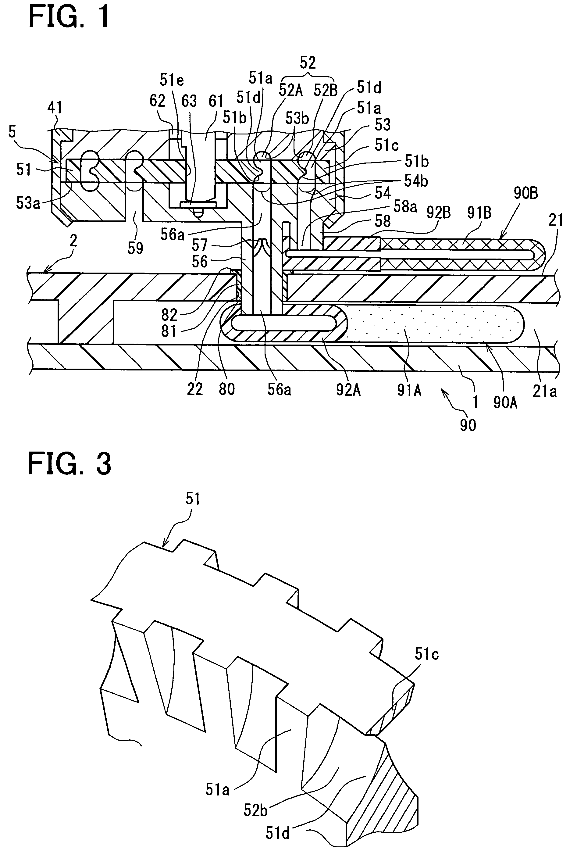
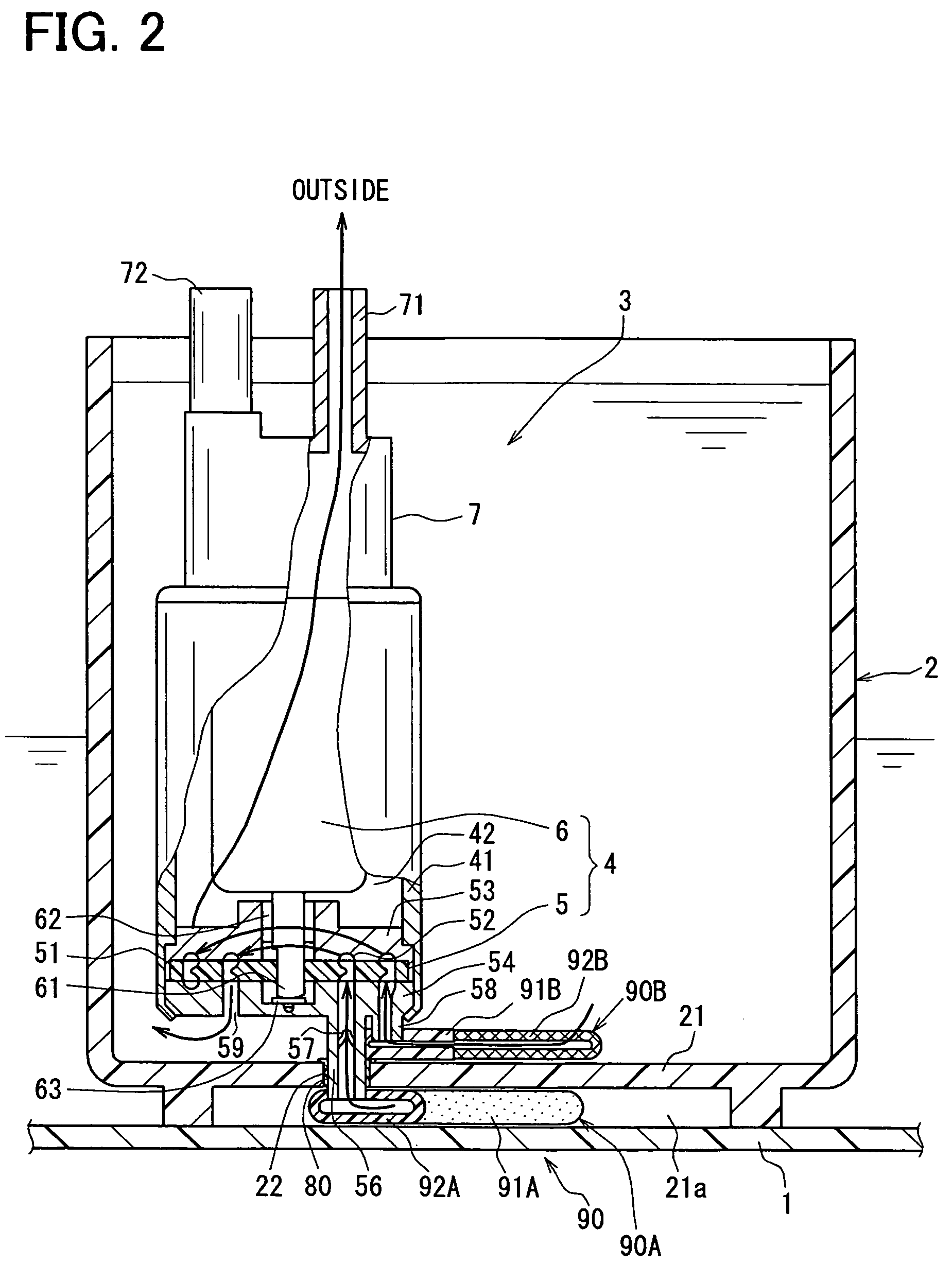
[0074]As shown in FIG. 4, a first projection 123 is provided to the bottom portion 21 in this second embodiment. An elastic member 80 having a cylindrical portion 81 and a first flange 82 is arranged between the outer periphery of the first projection 123 and the inner periphery of a suction pipe 56. The first projection 123, which is provided to the bottom portion 21, is in a substantially cylindrical shape. The first projection 123 extends toward a fuel pump 3. A through-hole 122 is defined in the first projection 123. The height, by which the first projection 123 projects from the bottom portion 21, is greater than the thickness of the bottom portion 21 in this embodiment. The height of the first projection 123 may be equal to or less than the thickness of the bottom portion 21.
[0075]A second projection 124 is provided to the end surface of the bottom portion 21 opposite to the first projection 123. The second projection 124 is cylindrical to extend toward the fuel tank 1. The fi...
third embodiment
[0082]As shown in FIG. 5, a filter 190A has a sleeve 93. The outer periphery of the sleeve 93 is fitted onto the inner periphery of a suction pipe 56, so that the filter 190A is mounted to the suction pipe 56.
[0083]The outer periphery of the sleeve 93 of the filter 190A is fitted into the inner periphery of the suction pipe 56.
[0084]The sleeve 93 projects from the upper end surface of a mount member 92A. The upper end surface of the mount member 92A abuts against the end surface of the suction pipe 56 on the side of the fuel tank 1 whereby the mount position of the filter 190A is fixed relative to the suction pipe 56. This construction also produces the same effect as in the first embodiment.
fourth embodiment
[0085]As shown in FIG. 6, a sleeve 93 and an elastic member 80 are interposed between the through-hole 22 of the bottom portion 21 and the outer periphery of the suction pipe 56. The elastic member 80 is tightly fitted between the inner periphery of the through-hole 22 of the bottom portion 21 and the outer periphery of the sleeve 93 of a filter 190A. The inner periphery of the sleeve 93 and the outer periphery of the suction pipe 56 fit mutually thereby connecting with each other. Preferably, the same material is used for both the sleeve 93 and the suction pipe 56. This construction also produces the same effect as in the first embodiment.
PUM
 Abstract
Description
Claims
Application Information
 - R&D
- Intellectual Property
- Life Sciences
- Materials
- Tech Scout
- Unparalleled Data Quality
- Higher Quality Content
- 60% Fewer Hallucinations
Browse by: Latest US Patents, China's latest patents, Technical Efficacy Thesaurus, Application Domain, Technology Topic, Popular Technical Reports.
© 2025 PatSnap. All rights reserved.Legal|Privacy policy|Modern Slavery Act Transparency Statement|Sitemap|About US| Contact US: help@patsnap.com


