Terminal-to-terminal communication connection control method using IP transfer network

a communication connection and control method technology, applied in data switching networks, data switching details, digital transmission, etc., can solve problems such as source routers being brought into overload conditions, and finally shutting down, so as to prevent congestion of ip transfer networks, suppress unfair user occurrences, and improve information security performan

Inactive Publication Date: 2007-11-27
DISTRIBUTION SYST RES INST THE AN UNDIVIDED 60 INTEREST +1
View PDF66 Cites 19 Cited by
  • Summary
  • Abstract
  • Description
  • Claims
  • Application Information

AI Technical Summary

Benefits of technology

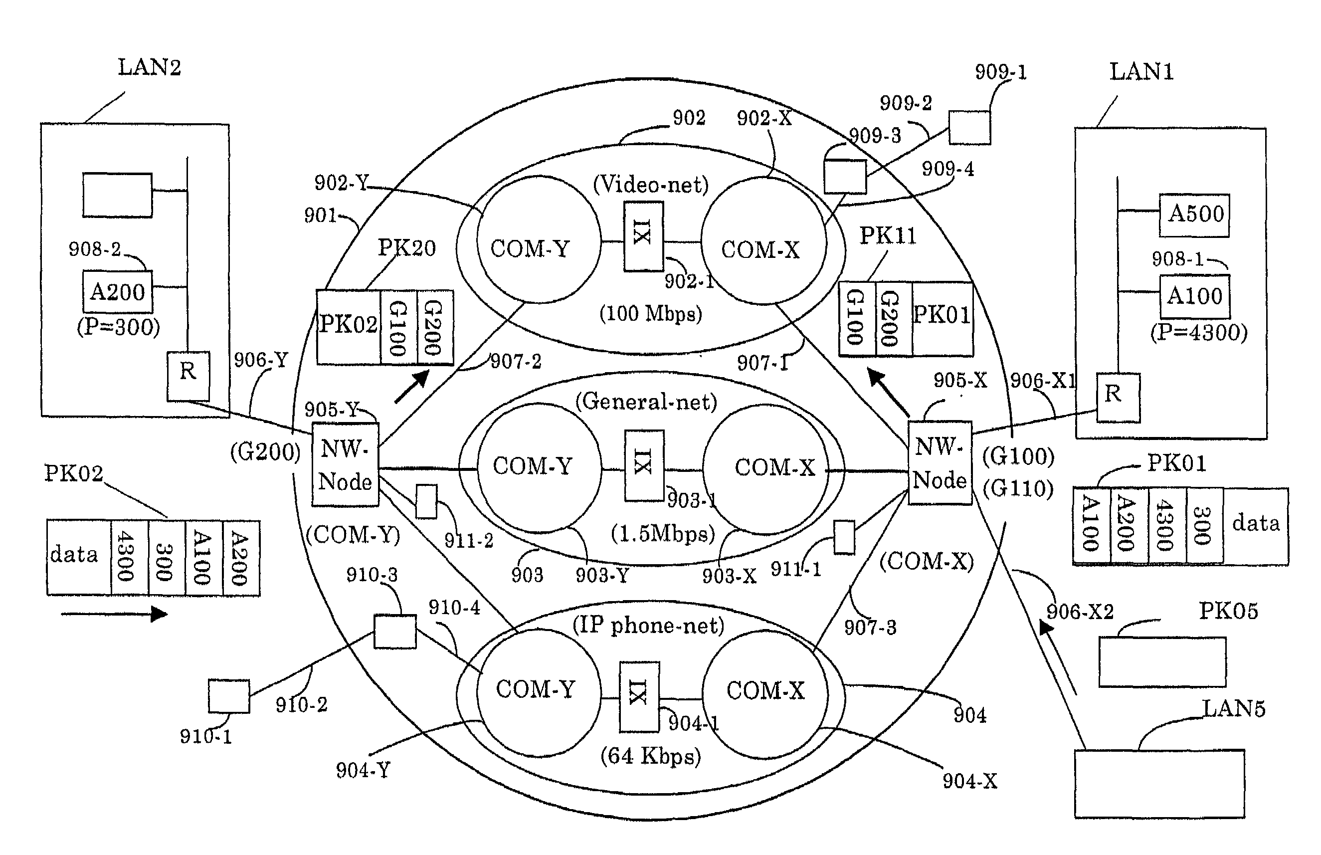
[0058]The present invention is featured by that while an address management table is set to a network node apparatus employed in an IP transfer network, the means for registering an address of a terminal into this address management table (refer to Japanese Patent Application No. 128956 / 1999) is applied to the multicast technique, which will now be described. As a network in which an IP transfer network is operated / managed by a communication company, a network node apparatus is provided in this IP transfer network. Since the IP addresses of the IP terminals are registered into the network node apparatus, the IP packet transmission by the multicast method with improving the information security performance can be realized. When such an IP packet containing a multicast IP address which is not yet registered into the network node apparatus is received, this received IP packet is discarded (IP address filtering operation).
[0060]As a first IP packet acceptance check, a check is made as to whether or not a destination IP address contained in a header of an external IP packet which is entered into an IP transfer network is registered into the address management table of the node apparatus. In the case that the destination IP address is not registered, this IP packet is discarded. As a second IP packet acceptance check, a check is made as to whether or not a transmission source IP address contained in a header of an external IP packet which is entered into an IP transfer network is registered into the address management table of the node apparatus. In the case that the destination IP address is not registered, this IP packet is discarded. As a first address registration check, while a destination multicast address is registered into the address management table of the network node apparatus, in such a case that a destination multicast address contained in a header of an external IP packet entered into the network node apparatus is not registered into the address management table, the network node apparatus discards the entered IP packet. As a result, it is possible to avoid such a condition that an unexpected IP packet is mixed into the IP transfer network. Also, since an address of a multicast transmission person is not allowed to be registered into an address management table of a network node apparatus of a packet reception person, an ACK packet cannot pass through the network node apparatus. The ACK packet is sent so as to confirm a reception of an IP packet, and is directed from the multicast IP packet reception person to the multicast IP packet transmission person. As a consequence, it is possible to prevent an occurrence of congestion of the IP transfer network, which is caused by ACK implosion of these ACK packets.
[0061]Also, while an IP address of a router is not allowed to be registered as a destination address, a dangerous IP packet is not sent out from an IP transfer network to a router of the IP transfer network. The dangerous IP packet may mistakenly rewrite a content of a multicast table. Alternatively, while an IP address of an operation management server for multicast operation provided in an IP transfer network is not allowed to be registered, such an access operation from the IP transfer net work into the operation management server employed in the IP transfer network cannot be carried out, so that the information security performance can be improved. As a second address registration check, a transmission source of an IP packet containing multicast data is limited, so that an occurrence of unfair user can be suppressed. Also, in such a case that unfair action is carried out, an IP packet transmission source can be easily specified, so that the information security performance of the IP transfer network can be improved.

Problems solved by technology

However, in the multicast system, since any of the IP terminals may constitute the transmission source for transmitting the multicast data, the following risk may occur.
There is another risk that since multicast tables contained in routers are rewritten and / or a very large amount of data are supplied into routers in an endless manner, source routers are brought into overload conditions, and finally shut down.

Method used


Image

  • Terminal-to-terminal communication connection control method using IP transfer network
  • Terminal-to-terminal communication connection control method using IP transfer network
  • Terminal-to-terminal communication connection control method using IP transfer network

Examples


first embodiment

1. First Embodiment Using Media Router

[0447]In FIG. 20, reference numeral 2 shows an integrated IP transfer network, reference numeral 3 indicates an IP data network, reference numeral 4 represents an IP telephone network, reference numeral 5-1 denotes an IP voice / image network, reference numeral 5-2 shows a best effort network, reference numeral 6-1 indicates a range of an IP transfer network operated / managed by a communication company “X”, and reference numeral 6-2 represents a range of an IP transfer network operated / managed by a communication company “Y”. Also, reference numerals 7-1, 7-2, 7-3, 7-4, 8-1, 8-2, 8-3 and 8-4 show a network node apparatus, respectively. Reference numerals 9-1 and 9-2 represent gateways. Reference numerals 10-1 to 10-8 show communication lines, reference numerals 11-1 to 11-10 denote IP terminals, reference numerals 12-1 and 12-2 show independent type IP telephone sets, and reference numerals 13-1 to 13-4 represent dependent type IP telephone sets. Fu...

second embodiment

2. Second Embodiment Using Gateway

>

[0526]Both the media routers 14-1 and 14-2 shown in FIG. 23 and FIG. 24 own the substantially same internal arrangements and also functions as those of a gateway 9-1 shown in FIG. 68 and of a gateway 9-2 indicated in FIG. 69. There are the below-mentioned technical different points. That is, the media routers 14-1 and 14-2 are provided outside the integrated IP transfer network 2, whereas the gateways 9-1 and 9-2 are provided inside the integrated IP transfer network 2. Also, charging units 72-1 and 72-2 are provided inside the gateways 9-land 9-2. Each internal structure of the media routers 14-11, 14-2 and the gateways 9-1, 9-2 is constituted by common internal element blocks such as an SCN interface, an H323 termination unit, a connection control unit and a router. Also, reference numeral 79-1 shows a RAS mechanism of the gateway 9-1, reference numeral 80-1 denotes an information process mechanism of the gateway 9-1, and reference numeral 81-1 s...

third embodiment

3. Third Embodiment Using Media Router Inside CATV Communication Network

[0547]Referring now to FIG. 88, a description will be made of a third embodiment featured by that since the media router according to the present invention is used inside a CATV communication network, terminals are communicated / connected to each other with employment of an IP transfer network.

[0548]A media router 115 is located within a CATV gateway 113-2 employed inside a CATV network 113-1, and is connected via a communication 112 to a network node apparatus 111 provided in an integrated IP transfer network 110. Also, the media router 115 is connected via any one of a CATV line interface 114, and CATV lines 119-1 through 119-4 to IP terminals 116-1 through 116-3; an analog telephone set 117, a dependent type IP telephone set 118-1, and a dependent type IP voice / image apparatus 118-2. The CATV lines 119-1 to 119-4 contain communication lower layers (namely, communication physical layer and data link layer) spec...


PUM


Abstract

Both a connection server and a relay connection server are installed in an IP transfer network; a function similar to a line connection control of a subscriber exchanger is applied to a connection server; a function similar to a line connection control of a relay exchanger is applied to the relay connection server; and a terminal-to-terminal communication connection control method with using the IP transfer network is realized in such a manner that a telephone set and a terminal such as an IP terminal and a video terminal transmit / receive an initial address message, an address completion message, a call pass message, a response message, a release message and a release completion message, which can be made in a 1-to-1 correspondence relationship with line connection control messages of the common line signal system. Furthermore, while an address administration table is set to a network node apparatus of an IP transfer network, means for registering addresses of the terminals into this address administration table is employed, so that an IP packet communication by a multicast manner can be realized with improving information security performance.

Description

BACKGROUND OF THE INVENTION[0001]1. Field of the Invention[0002]The present invention is related to a terminal-to-terminal (inter-terminal) communication connection control method using an IP (Internet Protocol) transfer network, which is applicable to an IP communication established between two terminal units such as an IP terminal, an IP telephone, and a voice / image apparatus (audio / visual apparatus), and also applicable to a 1:n type IP communication utilizing a multicast IP technique.[0003]2. Description of the Prior Art[0004]As a method capable of realizing various terminal-to-terminal communications such as mail transmissions / receptions, telephone, and image communications while an IP transfer network is utilized, Japanese Patent Application No. 128956 / 1999 (will be referred to as a “prior patent application” hereinafter) has been filed by the Applicant. This prior patent application discloses the method of realizing “integrated IP transfer network” containing therein a plural...

Claims


Application Information

Patent Timeline
Patent Type & Authority Patents(United States)
IPC IPC(8): H04L12/28H04L12/66H04L12/70H04L29/06H04L29/12H04M3/00H04M7/00
CPCH04L65/1069H04L29/06027H04L29/12066H04L29/1216H04L29/12367H04L29/12377H04L29/12424H04L29/12462H04L29/125H04L61/1511H04L61/157H04L61/2514H04L61/2517H04L61/2535H04L61/255H04L61/2564H04M7/006H04L65/1043H04L65/4076H04L29/06H04L12/18H04L29/12933H04L61/6068H04L63/0236H04L63/08H04L61/4557H04L61/4511H04L2101/668H04L65/611H04L65/1104H04L9/40H04L65/1101
Inventor FURUKAWA, HISAOMIYAGUCHI, SHOJI
Owner DISTRIBUTION SYST RES INST THE AN UNDIVIDED 60 INTEREST
Why Eureka
Try Eureka