
Optometer

a technology of optometry and ophthalmology, which is applied in the field of optometry, can solve the problems of causing a misdiagnosis owing to erroneous recording contents, affecting the examination process, and affecting the subject and the examiner

Inactive Publication Date: 2009-06-23
KK TOPCON
View PDF12 Cites 9 Cited by
  • Summary
  • Abstract
  • Description
  • Claims
  • Application Information

AI Technical Summary

Benefits of technology

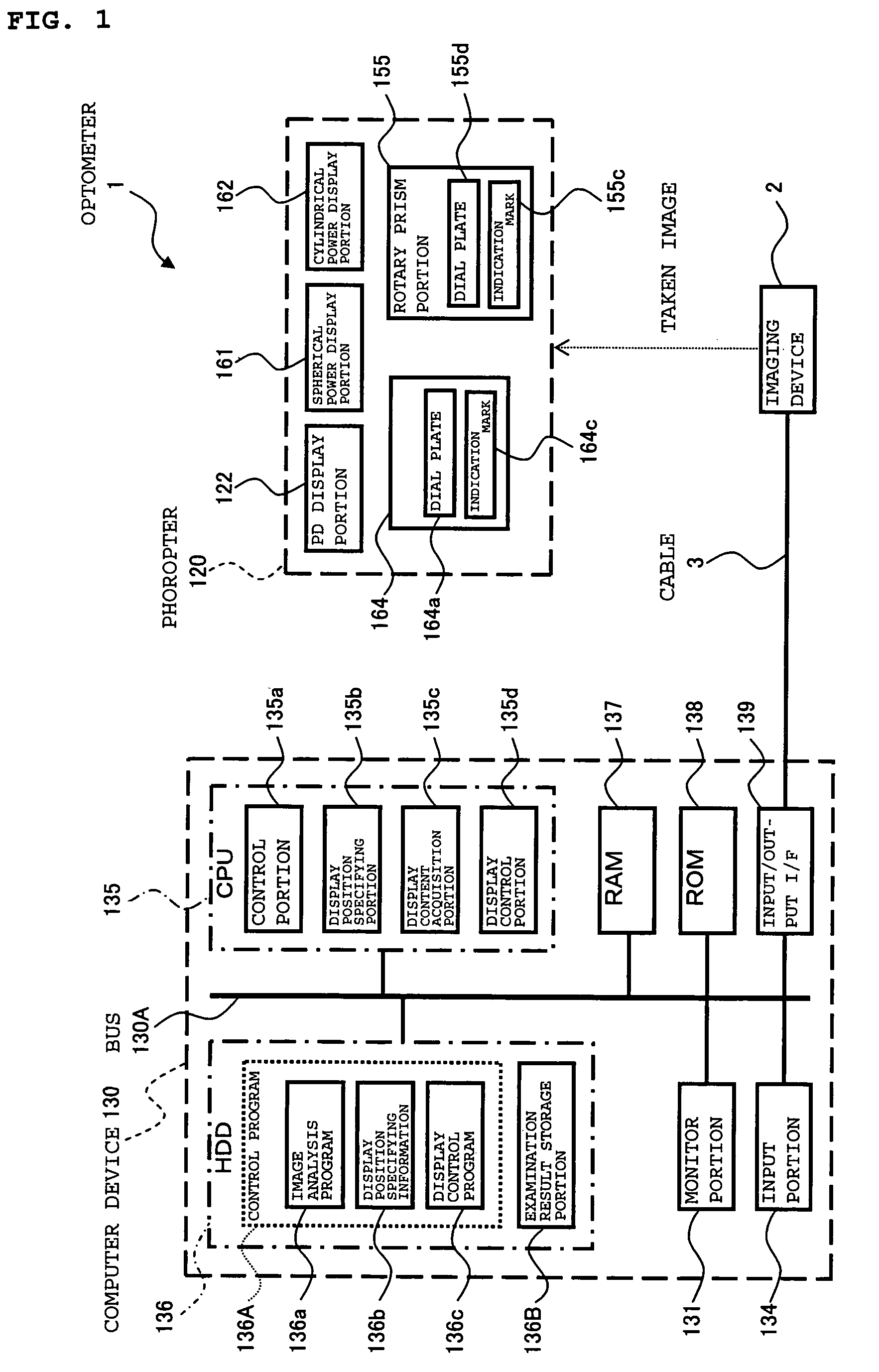
[0054]The optometer in accordance with the present invention includes the imaging means for taking the image, which includes the examination result display mechanism for displaying the examination result, and the image analysis means for analyzing the image taken by the imaging means and acquiring the examination result displayed on the examination result display mechanism. Accordingly, it is not necessary to visually read the displayed examination result, to enter the examination result to the computer device, or to write down the examination result in the recording sheet. Hence, even in the case of using the apparatus structured to mechanically display the examination result, the examination result can be recorded without making an error.

Problems solved by technology

However, in this conventional recording method, the displayed numeric values and the indicated scales are visually read, and accordingly, a reading error, an entering error, and a recording error are sometimes made.
If such an artificial error occurs, then a possibility to cause a misdiagnosis owing to erroneous recording contents may increase.
In addition, there is a possibility that a necessity of another examination occurs to burden the examiner and the subject.
Further, for the examiner who must examine many subjects a day, it is supposed to be heavily burdensome and merciless to be expected to eliminate such errors.

Method used


Image

  • Optometer
  • Optometer
  • Optometer

Examples


Embodiment Construction

[0072]A preferred embodiment of an optometer according to an embodiment of the present invention is described in detail with reference to the drawings.

[0073]The optometer of this embodiment has a substantially similar structure to the conventional optometer shown in FIGS. 11 to 16. Further, the optometer of this embodiment includes a phoropter or a trial frame as a subjective optometer. Constituents similar to those of the conventional optometer are described by using the reference numerals shown in FIGS. 11 to 16.

[0074]Further, as in the conventional optometer, an objective optometer (not shown) such as a refractometer is provided in the optometer of this embodiment. A measurement result by the objective optometer is automatically displayed on a monitor portion 131 of a computer device 130, and an examiner selects an initial value of a subjective optometry with reference to a value of the objective optometry.

[Apparatus Configuration]

[0075]FIG. 1 is a block diagram showing a structu...


PUM


Abstract

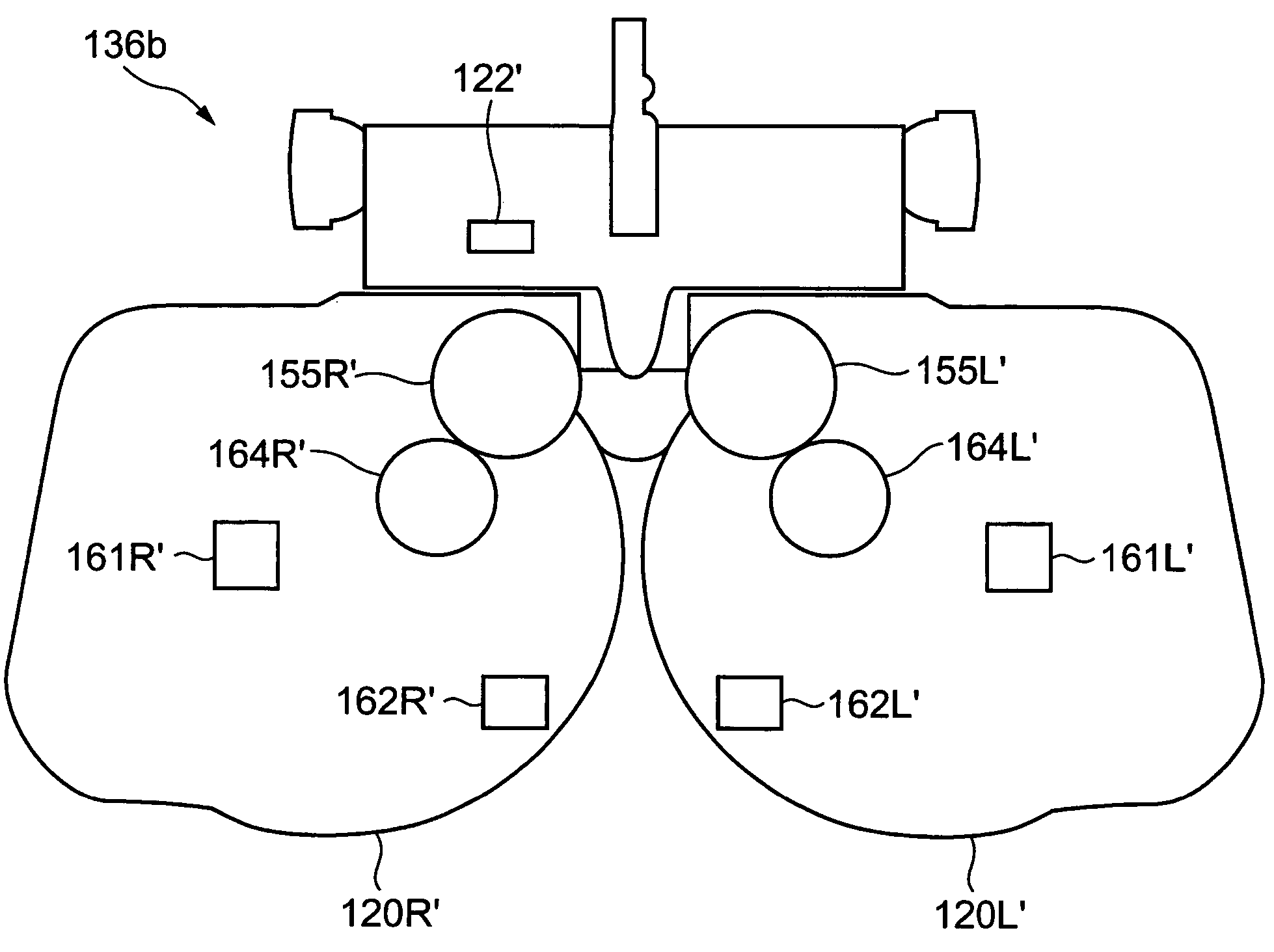
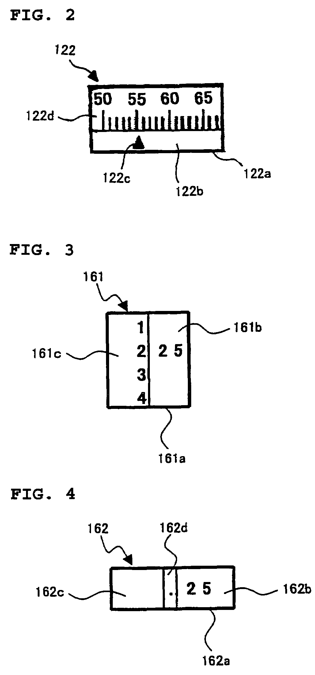
An optometer capable of recording an examination result without making an error even in a case of using an apparatus with a structure to mechanically display the examination result. The optometer includes a phoropter (120), an imaging device (2) for taking an image of the phoropter (120), the image including a display portion of the phoropter (120), a display position specifying portion (135b) for analyzing the taken image and specifying a position of the display portion in the taken image, a display content acquisition portion (135c) for acquiring display contents (examination results) of the display portion whose position is specified, and a display control portion (135d) for displaying the acquired examination results on a monitor portion (131). The display portion includes a PD display portion (122), a spherical power display portion (161), a spherical power display portion (162), a cylindrical axis display portion (164), and a rotary prism portion (155).

Description

BACKGROUND OF THE INVENTION[0001]1. Field of the Invention[0002]The present invention relates to an optometer for performing a refraction measurement of eyes to be examined, and more particularly to a technology for automatically inputting characters and symbols, which represent measurement values of a refractive power, an inter-pupil distance, and the like displayed on the optometer.[0003]2. Description of the Related Art[0004]In recent years, networking and automation of an optometer for use in an eyeglass shop have been progressing. However, for a phoropter, a trial frame, and the like, manual types, that is, manually operated types have been mainstreams because of merits in terms of operability, cost, and the like (for example, refer to JP 2002-315723 A, Paragraph Nos. 0007 and 0008 in Specification, and FIG. 1).[0005]FIG. 11 shows an example of a conventional optometer. An optometer 100 shown in the drawing is a system for performing a subjective measurement of eyes to be exami...

Claims


Application Information

Patent Timeline
Patent Type & Authority Patents(United States)
IPC IPC(8): A61B3/02
CPCA61B3/0041A61B3/0285
Inventor NAKAMURA, SHINICHIOGUSHI, HIROAKI
Owner KK TOPCON
Learn More