Corrective eyeglasses and method for subjective refraction by a wearer of said eyeglasses

a technology of subjective refraction and corrective eyeglasses, applied in the field of optometry, can solve the problems of unsatisfactory and substantial bulk of objects, unsatisfactory and unsatisfactory effects of corrective power, and unsatisfactory effects of subjective refraction

Active Publication Date: 2017-02-09
ESSILOR INT CIE GEN DOPTIQUE
View PDF6 Cites 3 Cited by
  • Summary
  • Abstract
  • Description
  • Claims
  • Application Information

AI Technical Summary

Benefits of technology

[0018]The spectacles can also comprise an energy (for example electrical) storage system making it possible to energize (electrically) means designed to adjust the spherical power of the third optical ele

Problems solved by technology

However, it will be understood that such an object has a substantial bulk and weight related to the number of lenses placed on each disc.
This solution is however rather impractical, particula

Method used


Image

  • Corrective eyeglasses and method for subjective refraction by a wearer of said eyeglasses
  • Corrective eyeglasses and method for subjective refraction by a wearer of said eyeglasses
  • Corrective eyeglasses and method for subjective refraction by a wearer of said eyeglasses

Examples


Embodiment Construction

[0026]The following description, given with regard to the appended drawings and by way of nonlimiting example, will allow what the invention consists of and how it can be carried out to be well understood.

[0027]In the appended drawings:

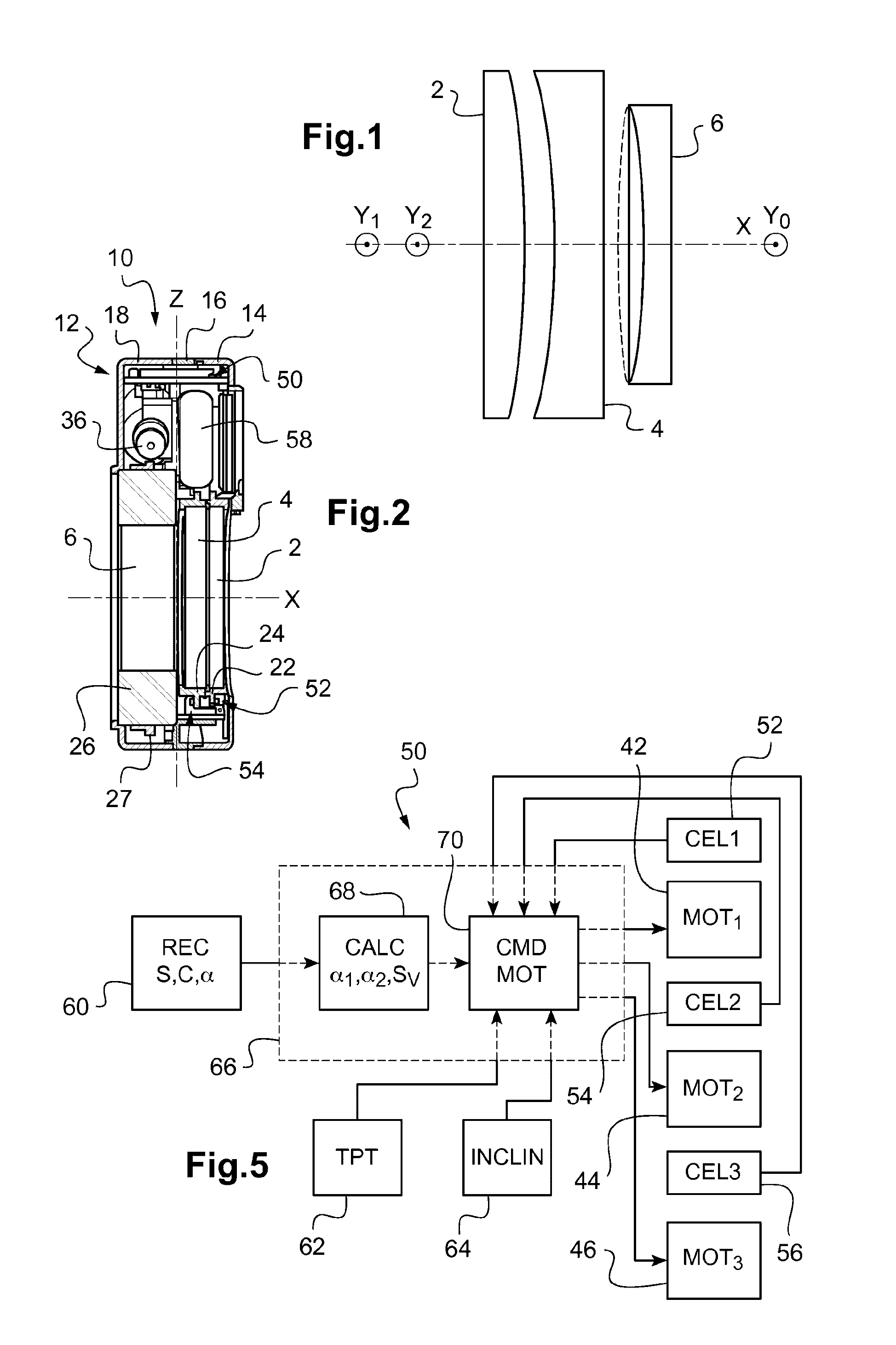
[0028]FIG. 1 schematically shows the optical elements used in one example implementation of the invention;

[0029]FIG. 2 shows a cross-sectional view of an example vision compensating device that may be used in the context of the invention;

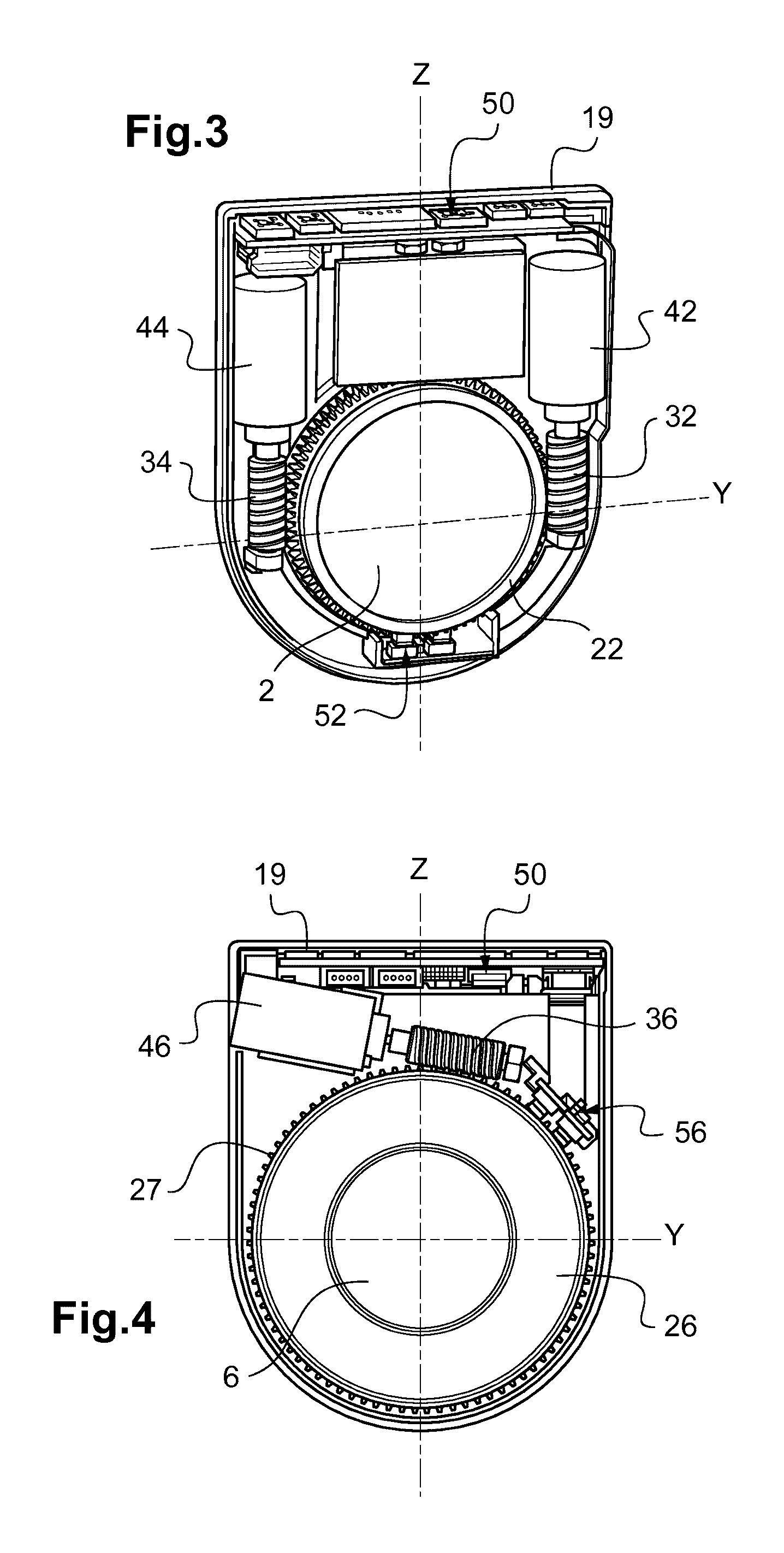
[0030]FIG. 3 shows a cutaway view of the vision compensating device in FIG. 2, on the cylindrical lens side;

[0031]FIG. 4 shows a cutaway view of the vision compensating device in FIG. 2, on the variable spherical lens side;

[0032]FIG. 5 schematically shows an element for controlling the vision compensating device in FIG. 2;

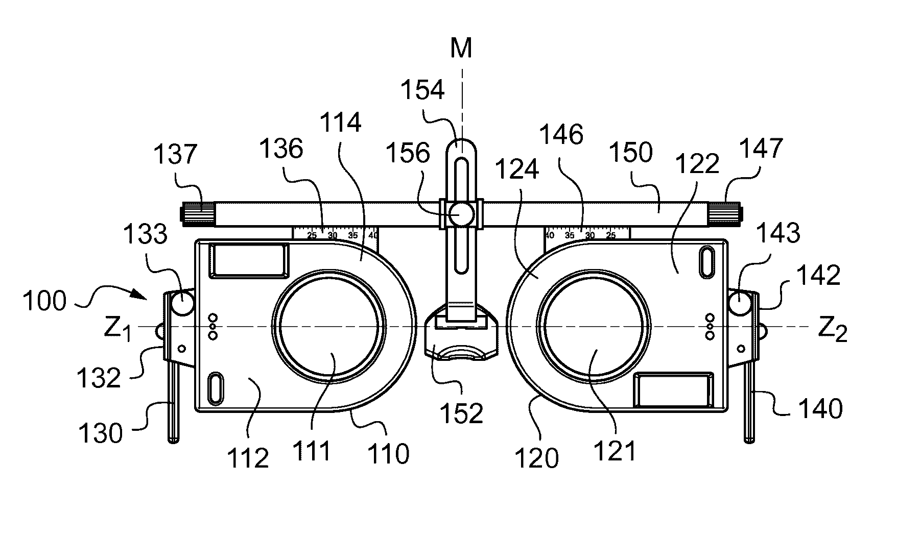
[0033]FIG. 6 represents in a side view a pair of trial spectacles using two vision compensating devices of the type of that represented in FIGS. 2 to 4;

[0034]FIG. 7 represents in an end-on view the p...


PUM


Abstract

The invention relates to vision compensating spectacles comprising means of support (130, 140, 152) on a wearer's face and at least one optical subassembly (110, 120) mounted on the support means (130, 140, 152) opposite at least one of the wearer's eyes.
The optical subassembly (110, 120) comprises three optical elements mounted on the support means in series along an optical axis: a first optical element of cylindrical power for a direction of gaze of the wearer along the optical axis, a second optical element of cylindrical power for the said direction of gaze and a third optical element of variable spherical power for the said direction of gaze.
The first optical element and the second optical element are adjustable in rotation about the optical axis independently of one another.

Description

TECHNICAL FIELD OF THE INVENTION[0001]The present invention relates to the field of optometry.[0002]It relates more particularly to vision compensating spectacles, for example trial spectacles, as well as to a method of subjective refraction of an individual wearing these spectacles.PRIOR ART[0003]In the context of the measurement of the visual acuity of a patient, it has already been proposed to simulate the visual compensation to be provided, for example by means of trial frames or a refractor such as a refraction head.[0004]In the refraction head, trial lenses are placed on a plurality of discs that are rotated manually or using a motorized mechanism. However, it will be understood that such an object has a substantial bulk and weight related to the number of lenses placed on each disc.[0005]Trial spectacles are less bulky. Provision is indeed made for them to successively receive trial lenses having different corrections, until the correction which is appropriate for the patient...

Claims


Application Information

Patent Timeline
IPC IPC(8): A61B3/04A61B3/00G02C13/00
CPCA61B3/04A61B3/0033A61B3/0025G02C13/003A61B3/028G02B7/023G02B7/12G02B27/027
Inventor BOUTINON, STEPHANETEJEDOR DEL RIO, VINCENTNAUCHE, MICHEL
Owner ESSILOR INT CIE GEN DOPTIQUE
Why Eureka
Try Eureka