Circuit for preventing corrosion of contact

a technology for preventing corrosion and contact, applied in the direction of resistance/reactance/impedence, contact forms, instruments, etc., can solve the problems of increasing contact resistance, affecting the operation of the contact, so as to achieve simple configuration, reduce the effect of corrosion prevention

Inactive Publication Date: 2009-06-23
FUJITSU GENERAL LTD
View PDF35 Cites 11 Cited by
  • Summary
  • Abstract
  • Description
  • Claims
  • Application Information

AI Technical Summary

Benefits of technology

[0013]The invention provides a circuit for preventing corrosion of a contact. The circuit can judge proceeding of corrosion of the contact appropriately with a simple configuration to ensure effective prevention of the corrosion. The circuit also can take measures against noise.
[0016]When the contact is closed, a part, which is electrically connected due to the closed state, influences on the potential of the signal line. On the other hand, when the contact is opened, there is no such influence on the potential of the signal line. Therefore, the state of the contact can be judged on a basis of the potential of the signal line. The comparator discriminates the potential of the signal line by comparing the potential of the signal line with the predetermined potential. The circuit described above judges whether or not the corrosion occurs by comparing the potential of the signal line, which is originally used for judging the connection state of the contact, with the predetermined potential. Therefore, it is not necessary for set dedicated logic. Also, the proceeding state of the corrosion of the contact can be judged appropriately and easily. For example, if it is known in advance that the closed / opened voltages of the contact can be judged at 0V and 5V, respectively, the predetermined potential is set between 0V and 5V. In JP-A-Hei.2-297818, it is necessary to set a potential to be compared and a reference voltage corresponding to the potential to be compared. Therefore, its configuration becomes complicate. When the potential of the signal line becomes a potential indicating occurrence of the corrosion, the comparing section activates (turns on) the switch and allows the corrosion-prevention current for the contact into the input terminal. Therefore, if the contact is brought into the closed state, the corrosion-prevention current flows and effective measure for corrosion-prevention can be provided. Also, by providing just one predetermined potential with the comparing section, the opened state / closed state of the contact can be known. Therefore, the single comparator has both a function of judging whether the contact is closed or opened and a function of judging whether or not the contact is corroded. Furthermore, the comparing section makes the input impedance to be low impedance. Therefore, a noise countermeasure such as EMI can be achieved. In other words, the corrosion prevention and the noise countermeasure can be provided with a simple configuration.

Problems solved by technology

There is a fear that such contacts may increase in contact resistance because a surface of a contact part is oxidized when a switch is turned off for disconnection.
Further, when a contact is connected for turning on, there is a fear that a surface of a part exposed around the contact part may be oxidized, the oxide which is then caught in the contact part, thereby causing a slight sliding wear resulting in an increased contact resistance.
An intermittent flow of a large current may contribute to malfunctions due to noise.
In addition, allowing a large current to flow into contacts may result in a greatly reduced electric life of contacts or adhesion of contacts.
Thus, there is a fear that the devices disclosed in the references may flow current for preventing corrosion even though corrosion does not occur or that the devices disclosed may flow insufficient current to prevent corrosion even if corrosion occurs.
However, if a point where the voltage is obtained is apart from the contact of the switch, there is a fear that the voltages may vary due to effects of noise.
Therefore, it is necessary for JP-A-Hei.2-297818 to provide a special logic, resulting in the complicated configuration.
Therefore, its configuration becomes complicate.

Method used


Image

  • Circuit for preventing corrosion of contact
  • Circuit for preventing corrosion of contact
  • Circuit for preventing corrosion of contact

Examples


Embodiment Construction

[0026]Respective embodiments of the invention will be described with reference to FIGS. 1 to 8. In each of the embodiments, the same reference numbers are given to parts equivalent to those for which a prior description is made, thereby omitting overlapping description. However, parts to which the same reference numbers are given are not necessarily structured in an exactly the same way. As a matter of course, various modifications may be made.

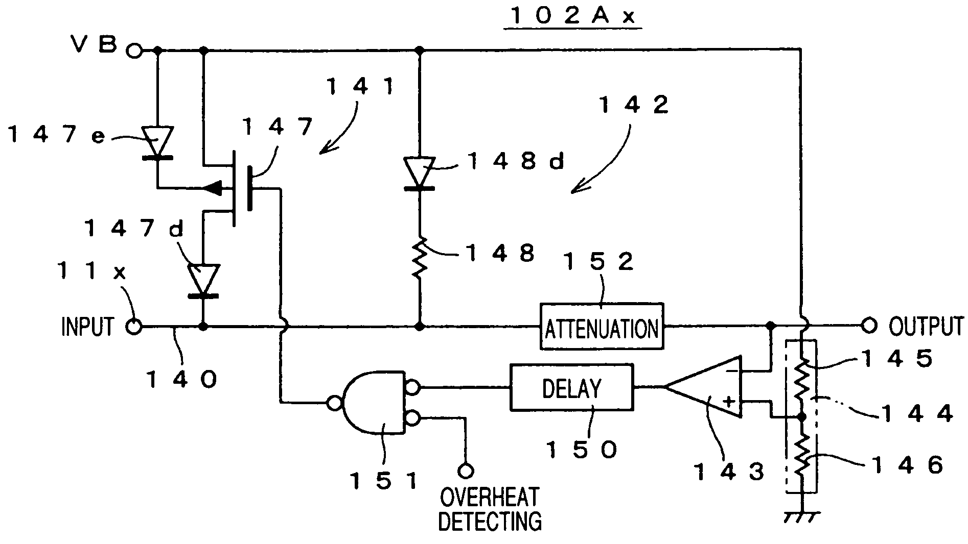
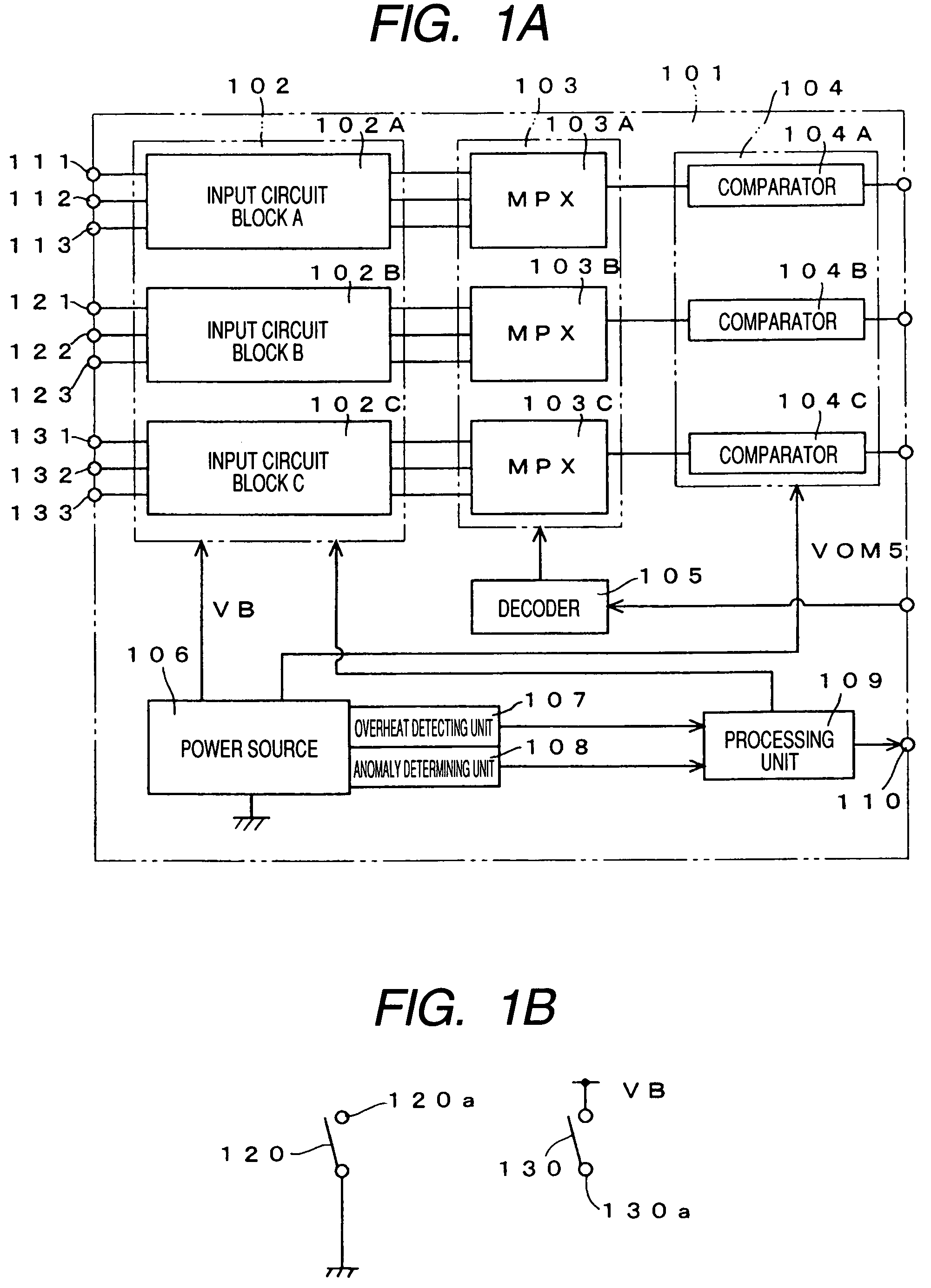
[0027]FIG. 1A shows a schematic electrical configuration of a circuit 101 for preventing corrosion of a contact according to an embodiment of the invention. FIG. 1B shows a connecting configuration between contacts. As shown in FIG. 1A, a circuit 101 for preventing corrosion of a contact is formed as a large-scale integrated circuit (“LSI”) having a function of selecting plural input signals. More specifically, the circuit 101 includes an input circuit block 102 having plural channels, selects output of the plural channels from the input circu...


PUM


Abstract

A circuit for preventing corrosion of a contact, includes an input terminal, a signal line, a switch, an impedance element, and a comparator. The input terminal is to be connected to the contact, which is outside the circuit. The signal line is connected to the input terminal. The switch is connected to the signal line. The impedance element is connected to the signal line in parallel to the switch. An impedance of the switching section is smaller than that of the impedance element. The comparator compares a potential of the signal line with a predetermined potential. The switch is turned on based on a comparison result output from the comparator.

Description

BACKGROUND[0001]1. Field of the Invention[0002]The present invention relates to a circuit for preventing corrosion of a contact, the circuit having a function of applying current to and destroying an oxide layer developed by corrosion on contacts at a switch or a connector.[0003]2. Description of the Related Art[0004]Contacts such as those of a switch or a connector have been made of a metal material excellent in electric conduction so as to reduce a contact resistance on electric connection. There is a fear that such contacts may increase in contact resistance because a surface of a contact part is oxidized when a switch is turned off for disconnection. Further, when a contact is connected for turning on, there is a fear that a surface of a part exposed around the contact part may be oxidized, the oxide which is then caught in the contact part, thereby causing a slight sliding wear resulting in an increased contact resistance. If a contact state and a non-contact state are appropri...

Claims


Application Information

Patent Timeline
Patent Type & Authority Patents(United States)
IPC IPC(8): H01H1/50H01H1/60H01H9/54
CPCH01H1/605H01H1/0015H01H2203/036H01H2239/032
Inventor KOMATSU, KAZUHIROFUJIMOTO, MASAHIKOOONISHI, KOUJIKIDO, KEISUKESAWADA, JUNICHI
Owner FUJITSU GENERAL LTD
Why Eureka
Try Eureka