Method and apparatus for preventing corrosion of contact

a technology of contact and corrosion prevention, applied in the direction of contact, excavation, foundation engineering, etc., can solve the problems of noise generation in the surrounding area, misjudge the opening of the contact, etc., to reduce the contact resistance, prevent the contact from being damaged, and suppress the influence of potential variation

Inactive Publication Date: 2005-10-20
FUJITSU GENERAL LTD
View PDF3 Cites 7 Cited by
  • Summary
  • Abstract
  • Description
  • Claims
  • Application Information

AI Technical Summary

Benefits of technology

[0013] According to one embodiment of the invention, a method for preventing corrosion of a contact includes comparing a potential of a signal line connected to the contact with a predetermined potential corresponding to the corrosion of the contact; flowing a corrosion-prevention current into the contact when a result of the comparing shows that the contact is corroded; and while the corrosion-prevention current is flown, suppressing influence of potential variation, which occurs in the signal line, on a subsequent circuit.
[0014] With this method, the potential of the signal line connected to the contact is compared with the predetermined potential corresponding to the corrosion of the contact. When the potential of the signal line is on one side with respect to the predetermined potential in a magnitude relation, a result of the comparing shows that the contact is corroded. At this time, the corrosion-prevention current is flown into the contact to remove the oxide from the contact and reduce the contact resistance, so that the contact is restored. That is, this method can prevent the corrosion of the contact. While the corrosion-prevention current is flown, influence of potential variation, which occurs in the signal line, on a subsequent circuit is suppressed. Therefore, even if the potential of the signal line varies due to flowing of the corrosion-prevention current, malfunction at a time of using the opened / closed state of the contact can be prevented.
[0015] According to one embodiment of the invention, a method for preventing corrosion of a contact, includes comparing a potential of a signal line connected to the contact with a predetermined potential corresponding to the corrosion of the contact; flowing a corrosion-prevention current into the contact when a result of the comparing shows that the contact is corroded; and reducing frequency of the flowing of the corrosion-prevention current.
[0016] With this method, the potential of the signal line connected to the contact is compared with the predetermined potential corresponding to the corrosion of the contact. When the potential of the signal line is on one side with respect to the predetermined potential in a magnitude relation, a result of the comparing shows that the contact is corroded. At this time, the corrosion-prevention current is flown into the contact to remove the oxide from the contact and reduce the contact resistance, so that the contact is restored. That is, this method can prevent the corrosion of the contact. Since the frequency of the flowing of the corrosion-prevention current is reduced, frequency of malfunction of the subsequent stage, which is associated with an operation of flowing the corrosion-prevention current. Therefore, the malfunction at a time of using the opened / closed state of the contact can be prevented.
[0017] According to one embodiment of the invention, a method for preventing corrosion of a contact includes comparing a potential of a signal line connected to the contact with a predetermined potential corresponding to the corrosion of the contact; flowing a corrosion-prevention current into the contact when a result of the comparing shows that the contact is corroded; and reducing an impedance of the signal line with respect to a noise.
[0018] With this method, the potential of the signal line connected to the contact is compared with the predetermined potential corresponding to the corrosion of the contact. When the potential of the signal line is on one side with respect to the predetermined potential in a magnitude relation, a result of the comparing shows that the contact is corroded. At this time, the corrosion-prevention current is flown into the contact to remove the oxide from the contact and reduce the contact resistance, so that the contact is restored. That is, this method can prevent the corrosion of the contact. Since the impedance of the signal line with respect to the noise is reduced, the noise resistance characteristic is improved. Also, the potential variation on the signal line due to the noise is suppressed. Therefore, the malfunction at a time of using the opened / closed state of the contact can be prevented.

Problems solved by technology

As a result, there is a fear that the subsequent stage may misjudge that the contact is in the opened state.
Also, if the corrosion-prevention current flows in the form of a pulse, noise may be generated in a surrounding area.

Method used


Image

  • Method and apparatus for preventing corrosion of contact
  • Method and apparatus for preventing corrosion of contact
  • Method and apparatus for preventing corrosion of contact

Examples


first embodiment

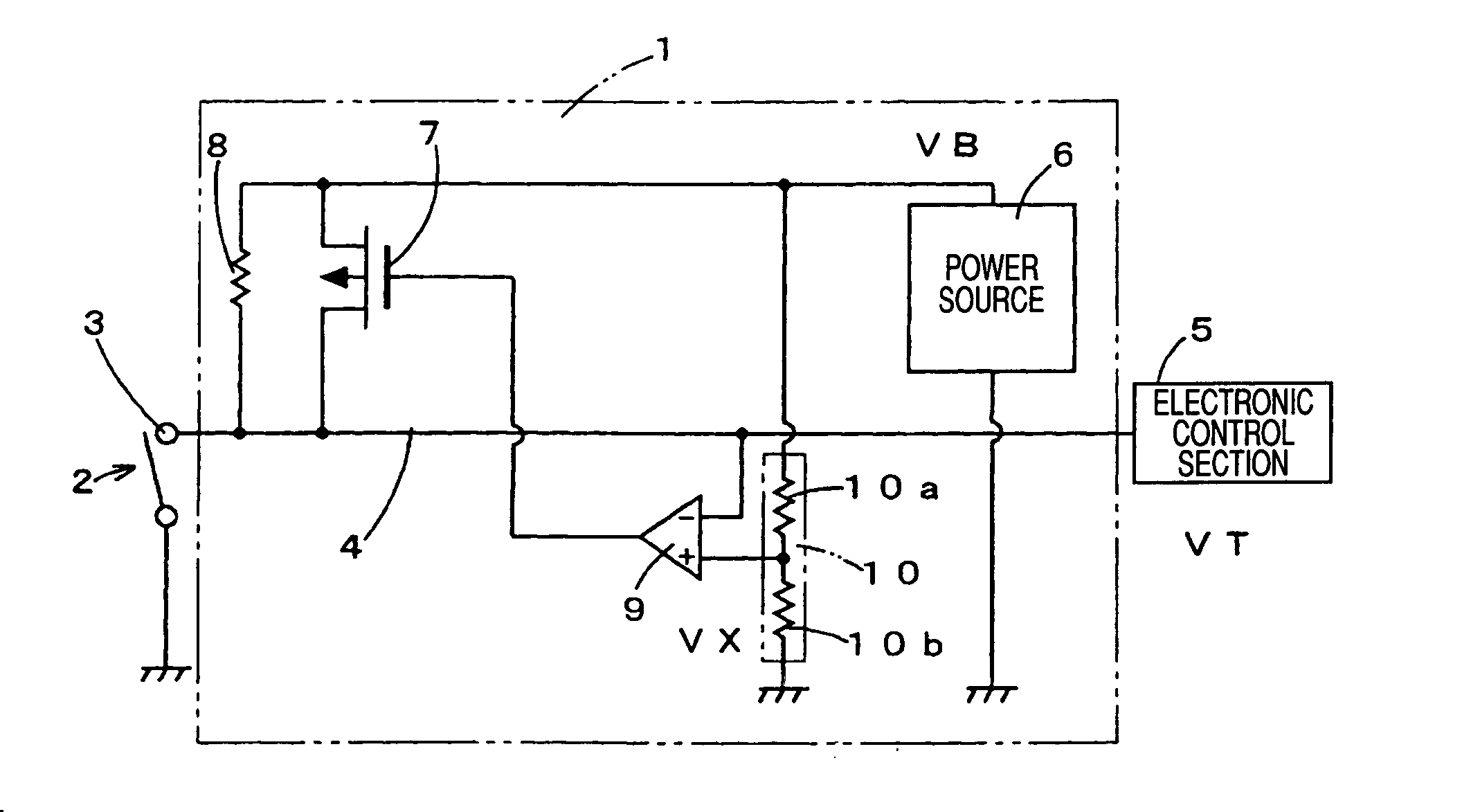
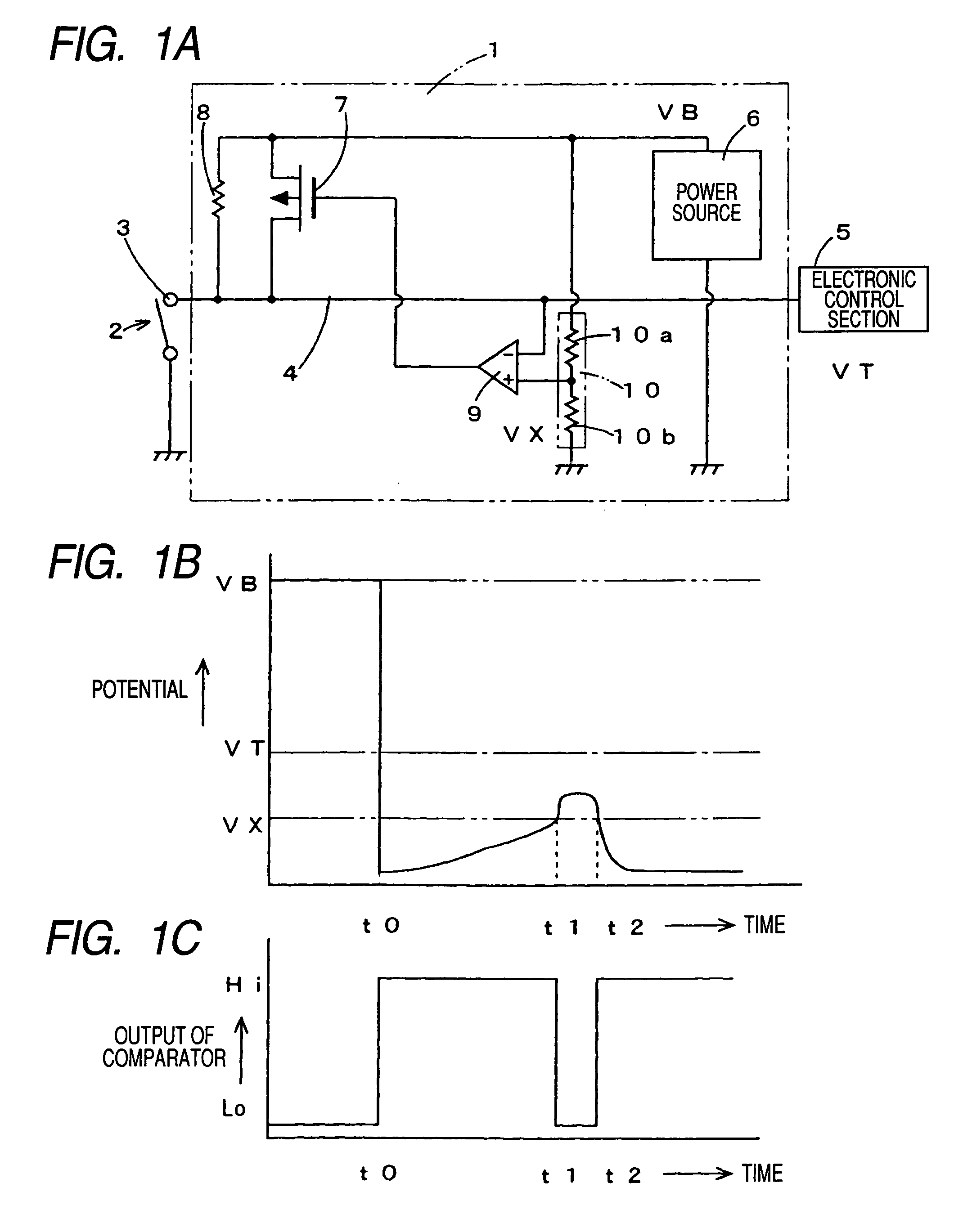
[0041]FIG. 1 illustrates a schematic electrical configuration of an apparatus 1 for preventing corrosion of a contact in accordance with the present invention and examples of operation. FIG. 1A illustrates the electrical configuration. The apparatus 1 for preventing corrosion of a contact has a function of preventing a contact 3 of a switch 2 from being corroded. The contact 3 is connected to an input side of a rearward electronic control section 5 via an input signal line 4. The contact 3 maybe a connector. The apparatus 1 for preventing corrosion of a contact is embodied as a part of a large-scale integrated circuit (LSI). A power source 6 generates, from power supplied externally of the LSI, a source voltage for operation of a logical circuit and then, supplies the generated source voltage to the interior of the LSI. The source voltage for operation of the logical circuit is, for example, 5V or 3.3V. The power source 6 is grounded at a low side and outputs the source voltage from...

second embodiment

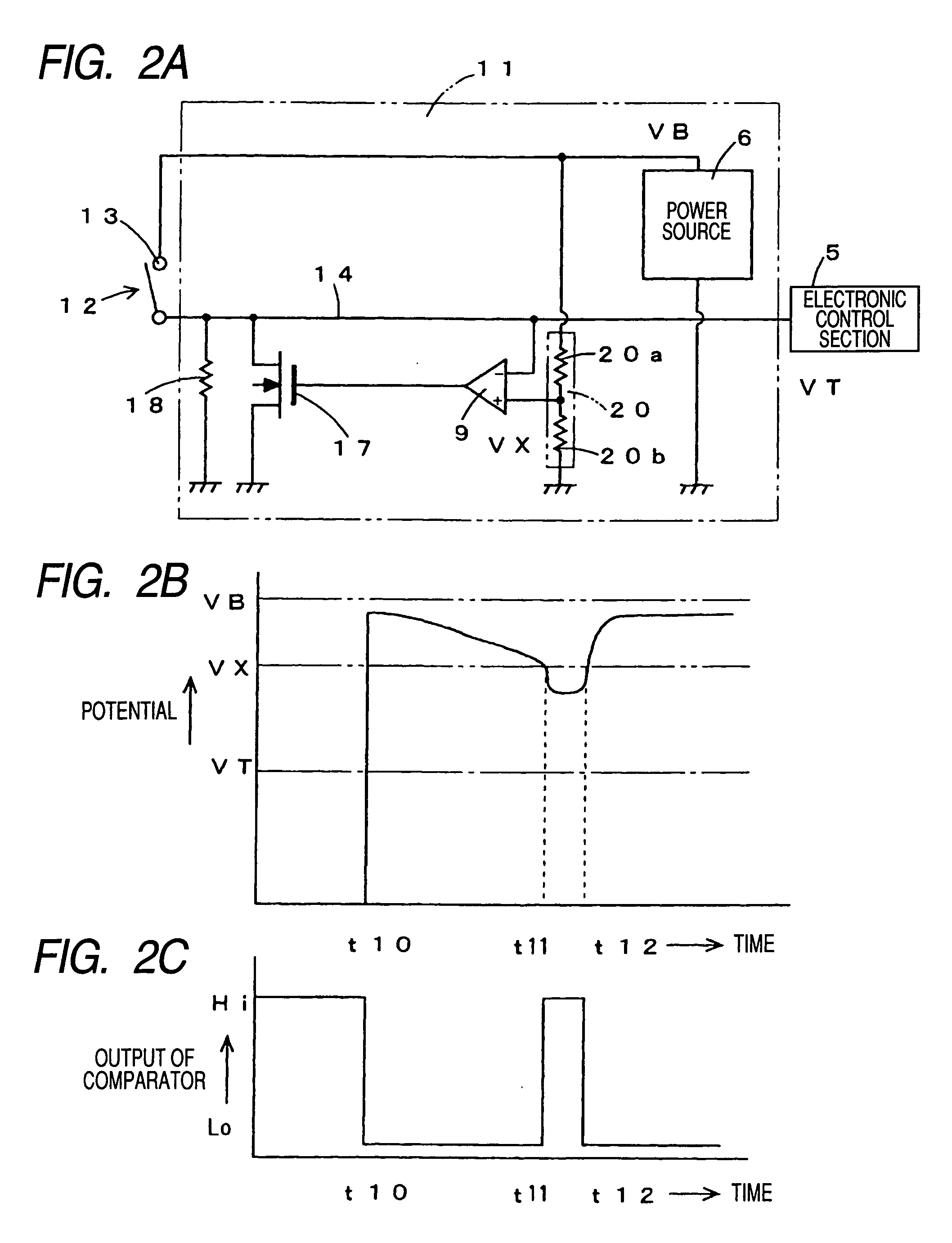
[0046]FIG. 2 illustrates a schematic electrical configuration of an apparatus 11 for preventing corrosion of a contact in accordance with the present invention and examples of operation. FIG. 2A illustrates the electrical configuration. The apparatus 11 for preventing corrosion of a contact has a function of preventing a contact 13 of a switch 12 from being corroded. The contact 13 is connected to an input side of a rearward electronic control section 5 via an input signal line 14. The contact 13 may be a connector. The apparatus 11 for preventing corrosion of a contact is embodied as a part of an LSI. A power source 6 generates, from power supplied externally of the LSI, a source voltage for operation of a logical circuit and then, supplies the generated source voltage to the interior of the LSI. The source voltage for operation of the logical circuit is, for example, 5V or 3.3V. The power source 6 is grounded at a low side and outputs the source voltage from a high side. Depending...

third embodiment

[0051]FIG. 3 illustrates a schematic electrical configuration of an apparatus 21 for preventing corrosion of a contact in accordance with the present invention. The apparatus 21 for preventing corrosion of a contact includes analog / digital (A / D) conversion section 22 for performing analog / digital conversion with respect to a signal input into the input signal line 4, and processing section 23 for comparing a conversion result of the analog / digital conversion section 22 with the predetermined potential VX to serve as a comparator and a processing unit for comparing the conversion result of the analog / digital conversion section 22 with the threshold level VT to thereby implementing logical judgment. In the case that the input signal line 4 is set as an input to the analog / digital conversion section 22, it is not necessary to separately provide a comparator and a logical judgment section, and by effectively using the conversion value of the analog / digital conversion section 22, it is p...


PUM


Abstract

A method for preventing corrosion of a contact, includes comparing a potential of a signal line connected to the contact with a predetermined potential corresponding to the corrosion of the contact; flowing a corrosion-prevention current into the contact when a result of the comparing shows that the contact is corroded; inputting into the signal line a signal used for judging a logical value of a connection state of the contact; and in the magnitude relation, setting the predetermined potential on another side of a threshold level used in the judging of the logical value of the connection state of the contact.

Description

BACKGROUND OF THE INVENTION [0001] 1. Field of the Invention [0002] The present invention relates to a method and an apparatus for preventing corrosion of a contact, which can break an oxide coating produced on a contact of a switch, a connector, etc. by applying a large current, thereby preventing the contact from being corroded. [0003] 2. Description of the Related Art [0004] As well known in the art, a contact of a switch, a connector, etc. is formed of a metallic material having high conductivity, so that small contact resistance is induced upon electrical connection. In the contact, under a non-connection state which corresponds to an off state, since a surface of the contacting portion is oxidized, contact resistance is likely to increase. Also, under a connection state, which corresponds to anon state, since a surface of a portion exposed around the contacting portion is oxidized, a produced oxide is likely to roll up toward the contacting portion to provoke fine sliding wear...

Claims


Application Information

Patent Timeline
Patent Type & Authority Applications(United States)
IPC IPC(8): H01H9/54H01H1/60
CPCH01H1/605E02D17/083E02D17/086
Inventor KOMATSU, KAZUHIROFUJIMOTO, MASAHIKOOONISHI, KOUJIKIDO, KEISUKESAWADA, JUNICHI
Owner FUJITSU GENERAL LTD
Why Eureka
Try Eureka