Motor vehicle axle component and method for producing a motor vehicle axle component

a technology for motor vehicles and axle components, applied in the direction of vehicle springs, pivoted suspension arms, lamination, etc., can solve the problems of high static and dynamic load on the joints of axle components, and achieve the effect of enhancing the adhesion and cost-effectiveness

Inactive Publication Date: 2013-04-09
BENTELER AUTOMOBILTECHNIK GMBH
View PDF19 Cites 7 Cited by
  • Summary
  • Abstract
  • Description
  • Claims
  • Application Information

AI Technical Summary

Benefits of technology

[0009]By constructing the joint zone according to the invention and purposely sealing the interior and exterior transition regions of the joint zone with an adhesive, the joint zone is protected against corrosion. This improves the load characteristic of the motor vehicle axle component and extends its service life. In particular when different metallic material pairs are employed, i.e., with the joint formed between a light metal body and a tubular body made of steel, contact corrosion can be prevented by sealing the contact region between the light metal and the steel with the adhesive.
[0031]Preferably, the end of the tubular body is moved into the receptacle until it stops, i.e., the tubular body is moved to a stop at an end face in or on the light metal body. With the application of the adhesive according to the invention and the available quantity of adhesive, the tubular component may also be pressed on by controlling the insertion depth, so that the end face of the tubular body makes partial contact with the frontally opposing face of the light metal body. In this way, the corrosion and leakage properties are not impaired in the transition region between the tubular body and the light metal body.

Problems solved by technology

The joint zones of the axle components are subjected to high static and dynamic loads during operation.

Method used


Image

  • Motor vehicle axle component and method for producing a motor vehicle axle component
  • Motor vehicle axle component and method for producing a motor vehicle axle component
  • Motor vehicle axle component and method for producing a motor vehicle axle component

Examples


Embodiment Construction

[0044]Throughout all the figures, same or corresponding elements may generally be indicated by same reference numerals. These depicted embodiments are to be understood as illustrative of the invention and not as limiting in any way. It should also be understood that the figures are not necessarily to scale and that the embodiments are sometimes illustrated by graphic symbols, phantom lines, diagrammatic representations and fragmentary views. In certain instances, details which are not necessary for an understanding of the present invention or which render other details difficult to perceive may have been omitted.

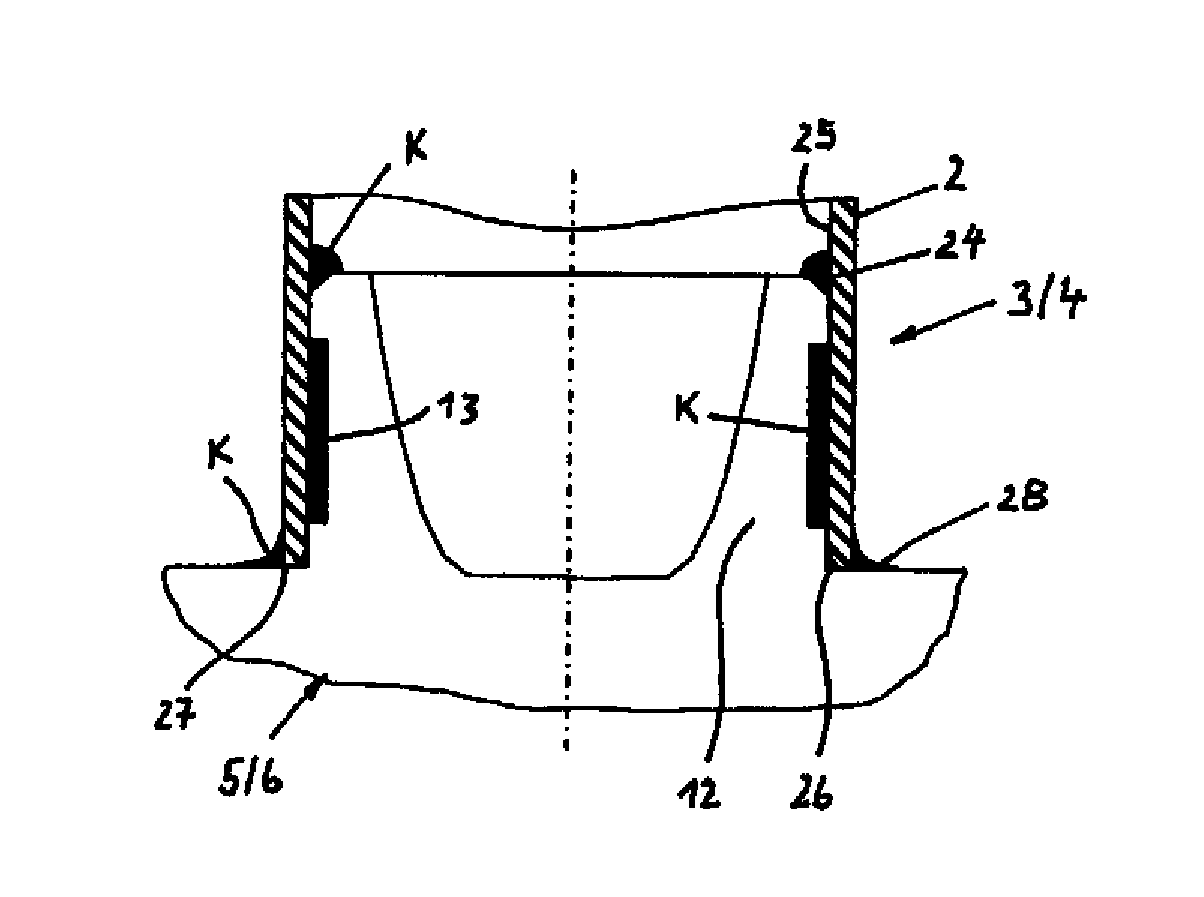
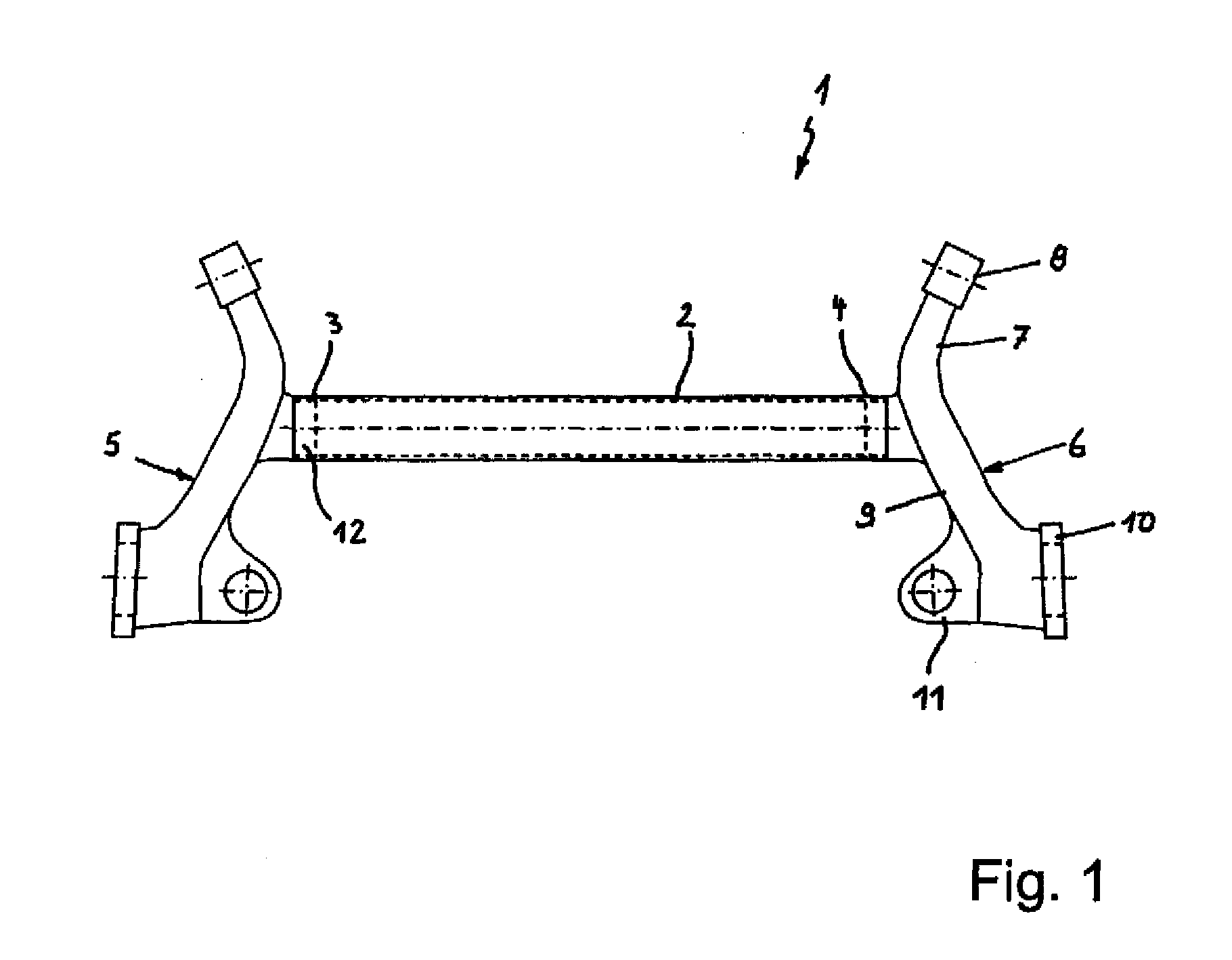
[0045]Turning now to the drawing, and in particular to FIG. 1, there is shown a motor vehicle axle component according to the invention in form of a torsion beam axle or dead beam axle 1.

[0046]The dead beam axle 1 has a tubular body 2 made of steel and operating as a torsion profile, with a respective light metal body 5, 6 adhesively joined at respective ends of the tubular ...


PUM

PropertyMeasurementUnit
angleaaaaaaaaaa
angleaaaaaaaaaa
angleaaaaaaaaaa

Abstract

The invention relates to a motor vehicle axle component and a method for producing a motor vehicle axle component. The axle component, for example a dead beam axle, includes a light metal body, such as aluminum or magnesium or corresponding alloys, and a tubular body in form of a steel tube, which are adhesively connected with each other. An adhesive pocket filled with an adhesive is formed between an end of the tubular body and a cylindrical receptacle of the light metal body. Respective bezels are arranged on a free end of the receptacle and on a free end of the tubular body. The spaces between the respective bezels and adjacent walls are filled with adhesive, which seals the interior and exterior transition regions of the joint zone, thus protecting the joint zone against corrosion, improving the load characteristic of the axle component and increasing its service life.

Description

CROSS-REFERENCES TO RELATED APPLICATIONS[0001]This application claims the priority of German Patent Application, Serial No. 10 2009 037 905.3, filed Aug. 19, 2009, pursuant to 35 U.S.C. 119(a)-(d), the content of which is incorporated herein by reference in its entirety as if fully set forth herein.BACKGROUND OF THE INVENTION[0002]The invention relates to a motor vehicle axle component with a light metal body and a tubular body, which are adhesively connected with one another, wherein an adhesive pocket filled with an adhesive is formed between one end of the tubular body and a cylindrical receptacle of the light metal body, and a method for producing such a motor vehicle axle component.[0003]The following discussion of related art is provided to assist the reader in understanding the advantages of the invention, and is not to be construed as an admission that this related art is prior art to this invention.[0004]The joint zones of the axle components are subjected to high static an...

Claims


Application Information

Patent Timeline
Patent Type & Authority Patents(United States)
IPC IPC(8): B60B35/00
CPCB60G7/001B60G21/051B60G21/055B60G2202/136Y10T156/1074B60G2206/20B60G2206/821B60G2206/92B60G2204/1226
Inventor WIBBEKE, MICHAELKROGMEIER, JURGEN
Owner BENTELER AUTOMOBILTECHNIK GMBH
Why Eureka
Try Eureka