Weatherproof connector

a technology of weatherproof connectors and connectors, applied in the direction of insulated conductors, coupling device connections, cables, etc., can solve problems such as overheating and fire, and achieve the effect of preventing overheating

Active Publication Date: 2009-06-30
SMITH KENNETH
View PDF2 Cites 30 Cited by
  • Summary
  • Abstract
  • Description
  • Claims
  • Application Information

AI Technical Summary

Benefits of technology

[0005]With the above-noted prior art in mind, an electric interconnect is provided wherein the mating of the two parts is predetermined by the configuration of the mating parts, thereby preventing any inadvertent incorrect interconnect.
[0006]Further the inventive device includes not only a more robust interconnect element, but also a failsafe securement method in addition to superior sealing from the weather.

Problems solved by technology

These known devices have been known to malfunction because of the continuous motion as on a boat, thereby causing overheating and perhaps fire.

Method used


Image

  • Weatherproof connector
  • Weatherproof connector
  • Weatherproof connector

Examples


Embodiment Construction

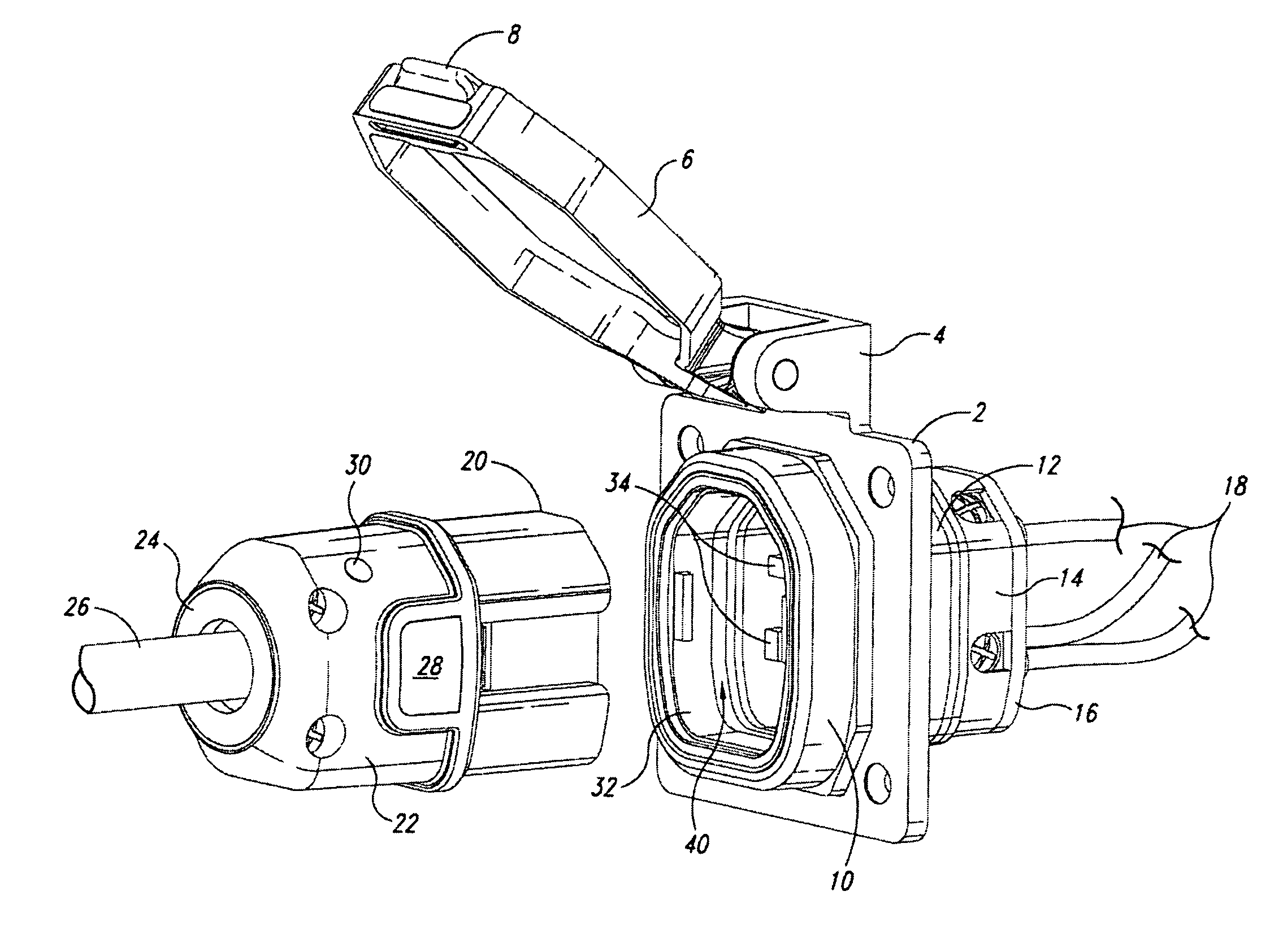
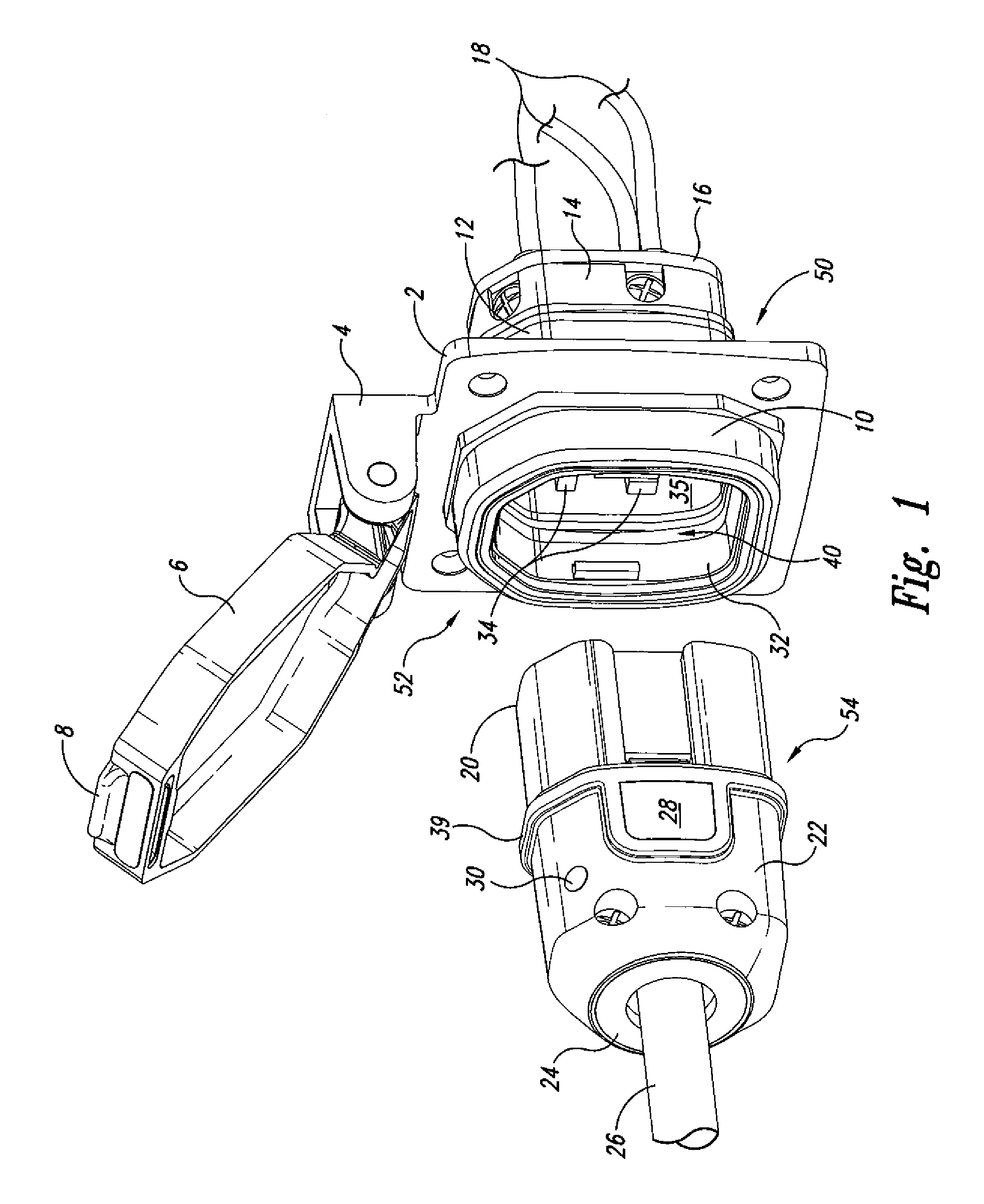
[0013]As seen in FIG. 1, the unit fixed to the vehicle or structure is a weatherproof power inlet or receptacle box 50 comprising a wall mounted female unit 52 which includes a mounting plate 2 for securement to a wall including an outwardly extending hinge element 4 to which is mounted a weather cover 6 including a latch 8. Secured to the mounting plate is front flange 10, a rear flange 12, a receptacle base 14 and a receptacle cover 16 through which extend a plurality of wires 18. Likewise seen in this view is a removable male unit or plug 54, the connector receptacle 20, the housing 22, the cap 24 and input wire26. Likewise seen in this view is a release button 28 and a light emitting diode (LED) 30.

[0014]The connector receptacle 20 is received within the opening 32 surrounded by the front flange 10. Further seen in this view are the male connector elements 34 which are robust extending outwardly from rear wall 35.

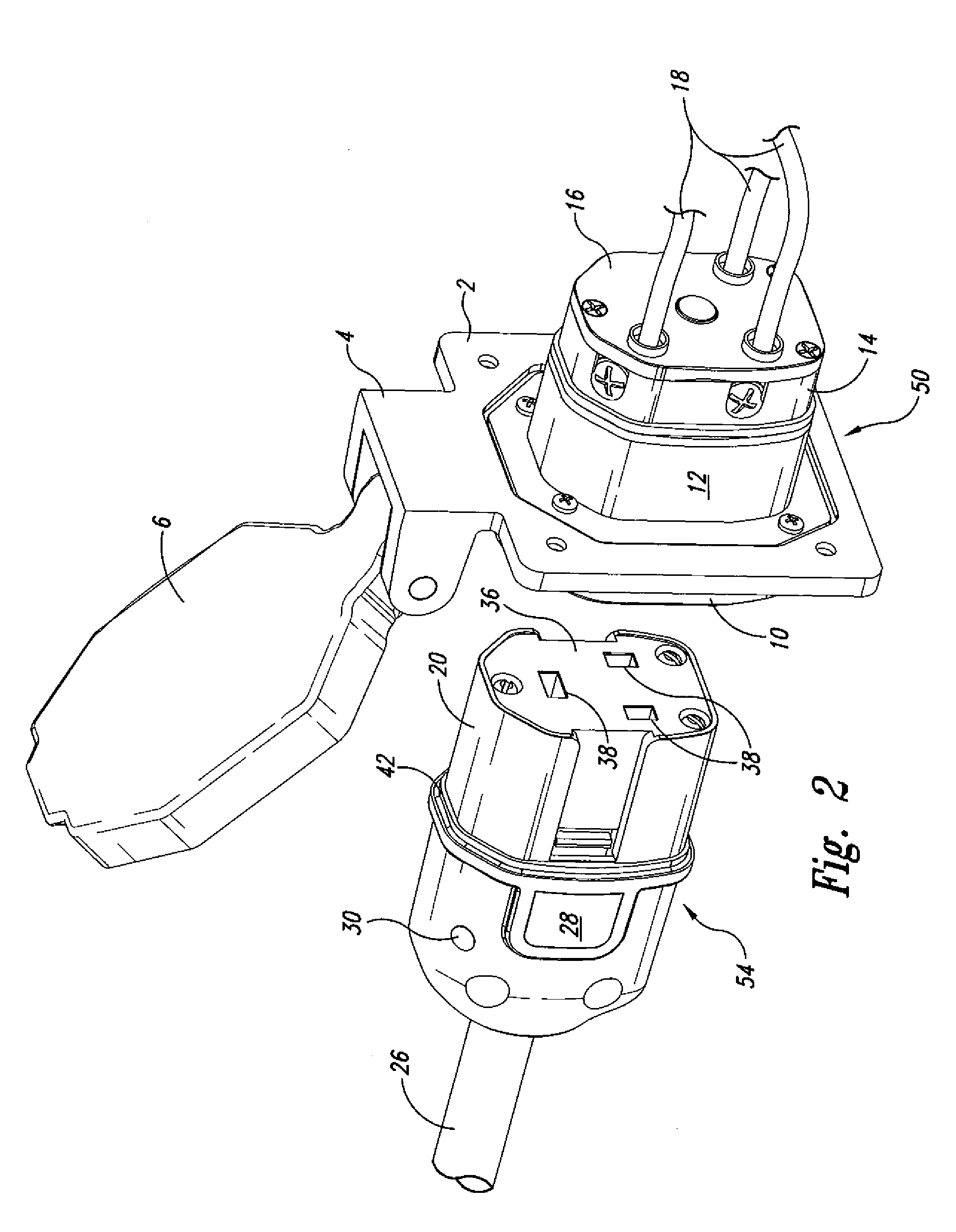
[0015]Referring now to FIG. 2, similar parts are identified with t...


PUM


Abstract

A weatherproof power inlet box and mating plug wherein the inlet box and mating plug are asymmetrical, positively latched and include more robust elements and a visual indicator of the status of the interconnect. Also included is a thermostat that trips to prevent overheating.

Description

TECHNICAL FIELD[0001]This invention relates to a weatherproof connector and more particularly to a weatherproof connector system wherein the electrical connector portions when properly connected, interlock to prevent accidental disconnect and visually indicate the status of the connection. Also incorporated is a thermostat to break connection in the event of overheating.BACKGROUND OF THE INVENTION[0002]Electrical interconnects have been available and are used principally to supply power to camping vehicles and boats when at dock. The standard electrical interconnect includes projecting prongs which must be aligned with the appropriate receptacle as well as a bayonet type securement device to prevent inadvertent dislodge of the interconnect. These known devices have been known to malfunction because of the continuous motion as on a boat, thereby causing overheating and perhaps fire. Examples of known interconnects are shown in U.S. Pat. No. 5,118,301, granted to Bentivolio Jun. 2, 19...

Claims


Application Information

Patent Timeline
Patent Type & Authority Patents(United States)
IPC IPC(8): H01H9/02
CPCH01R13/5213H01R13/5221
Inventor SMITH, KENNETH
Owner SMITH KENNETH
Why Eureka
Try Eureka