Weatherproof connector

a technology of connectors and weatherproof materials, applied in the direction of insulated conductors, coupling device connections, electrical apparatus casings/cabinets/drawers, etc., to achieve the effect of preventing overheating

Active Publication Date: 2009-04-02
SMITH KENNETH
View PDF10 Cites 32 Cited by
  • Summary
  • Abstract
  • Description
  • Claims
  • Application Information

AI Technical Summary

Benefits of technology

[0009]It also includes a thermos

Problems solved by technology

These known devices have been known to malfunction because of the continu

Method used


Image

  • Weatherproof connector
  • Weatherproof connector
  • Weatherproof connector

Examples


Embodiment Construction

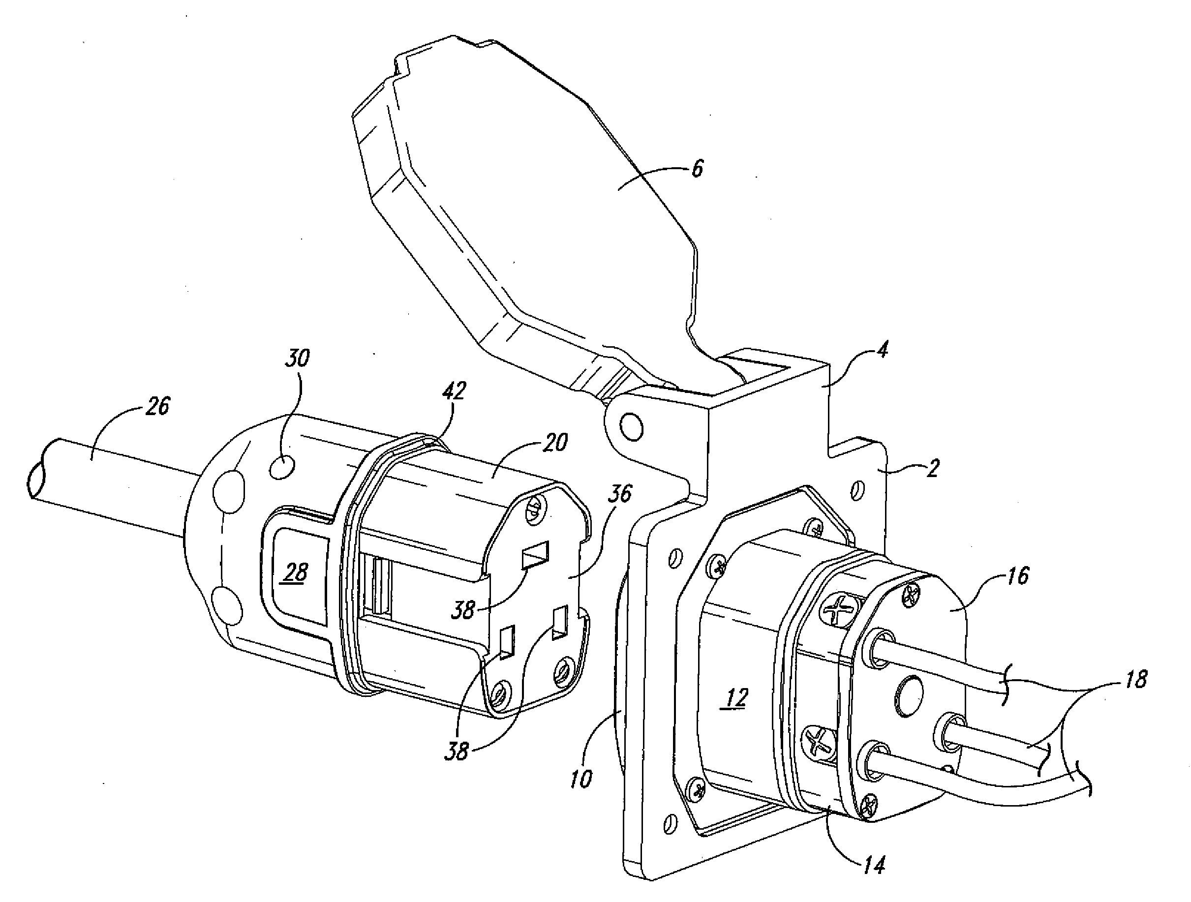
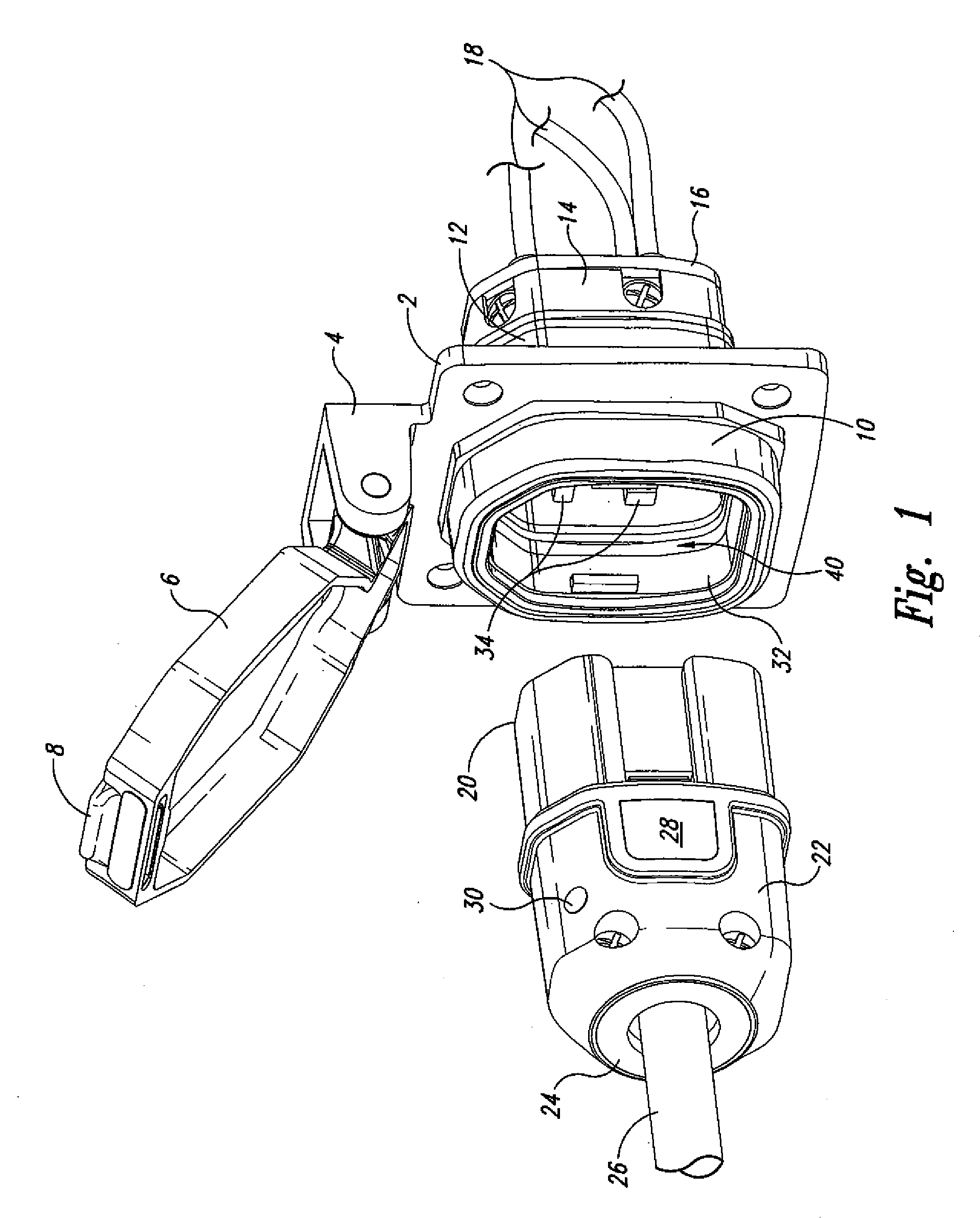
[0018]As seen in FIG. 1, the unit fixed to the vehicle or structure includes a mounting plate 2 for securement to a wall including an outwardly extending hinge element 4 to which is mounted a weather cover 6 including a latch 8. Secured to the mounting plate is front flange 10, a rear flange 12, a receptacle base 14 and a receptacle cover 16 through which extend a plurality of wires 18. Likewise seen in this view is the connector receptacle 20, the housing 22, the cap 24 and input wire 26. Likewise seen in this view are a release button 28 and an LED 30.

[0019]The connector receptacle 20 is received within the opening 32 surrounded by the front flange 10. Further seen in this view are the male connector elements 34 which are robust.

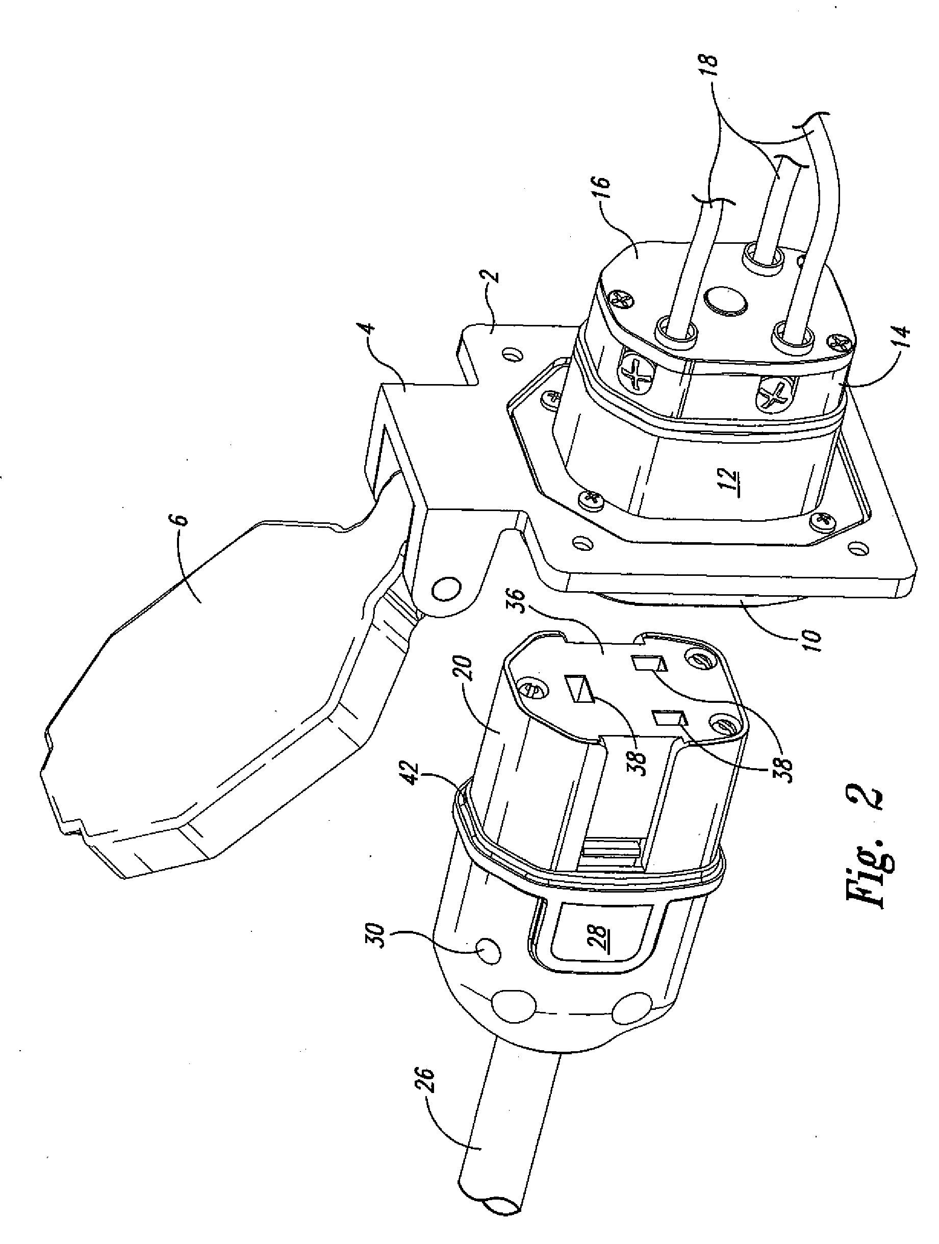
[0020]Referring now to FIG. 2, similar parts are identified with the identical number as in FIG. 1 and it is further to be seen that within the connector receptacle 20 is the actual connector 36 having openings 38 to receive male connector members 34.

[0021...


PUM


Abstract

A weatherproof power inlet box and mating plug wherein the inlet box and mating plug are asymmetrical, positively latched and include more robust elements and a visual indicator of the status of the interconnect. Also included is a thermostat that trips to prevent overheating.

Description

[0001]This application is a continuation-in-part of U.S. application Ser. No. 11 / 864,314.TECHNICAL FIELD[0002]This invention relates to a weatherproof connector and more particularly to a weatherproof connector system, wherein the electrical connector elements prevent misconnections and, when properly connected, interlock to prevent accidental disconnect, and visually indicate the status of the connection. Also incorporated is a thermostat to break connection in the unlikely event of overheating.BACKGROUND OF THE INVENTION[0003]Electrical interconnects have been available and are used principally to supply power to camping vehicles or motor homes when parked and boats when at dock. The standard electrical interconnect includes projecting prongs which must be aligned with the appropriate receptacle as well as including a bayonet type securement device to prevent inadvertent dislodge of the interconnect. These known devices have been known to malfunction because of the continuous moti...

Claims


Application Information

Patent Timeline
IPC IPC(8): H01R13/44H01R13/52
CPCH01R13/447H01R13/5205H01R13/5221H01R2103/00H01R13/748H01R24/30H01R24/78H01R13/652H01R13/639H01R13/66H01R2201/26
Inventor SMITH, KEN
Owner SMITH KENNETH
Why Eureka
Try Eureka