Wafer clamp having changeable supporting part

a technology of supporting parts and wafers, which is applied in the direction of pliers, thin material handling, electrical equipment, etc., can solve the problems of letting the wafer b>3/b> fall to the ground and be damaged, prior art does not fulfill all users' requests on actual use, etc., to prevent the wafer from falling, improve the wear resistance and smooth effect of the wafer

Inactive Publication Date: 2009-07-21
INST NUCLEAR ENERGY RES ROCAEC
View PDF7 Cites 0 Cited by
  • Summary
  • Abstract
  • Description
  • Claims
  • Application Information

AI Technical Summary

Benefits of technology

[0005]Another purpose of the present invention is to hinder the wafer from slipping and improve a wear resistance and a smoothness of the wafer with a simple structure, a good practicality and a wide application.

Problems solved by technology

Yet, when the wafer is clamped by a wafer clamp, an unevenness on the surface where the wafer clamp clamps, or a small are a for clamping, the wafer may slip to fall on the ground and become damaged.
However, both the clamping areas of the clamping part 32 and the supporting part 33 are too small, which may let the wafer 3 fall to the ground and be damaged.
Hence, the prior art does not fulfill all users requests on actual use.

Method used


Image

  • Wafer clamp having changeable supporting part
  • Wafer clamp having changeable supporting part
  • Wafer clamp having changeable supporting part

Examples


Embodiment Construction

[0015]The following descriptions of the preferred embodiments are provided to understand the features and the structures of the present invention.

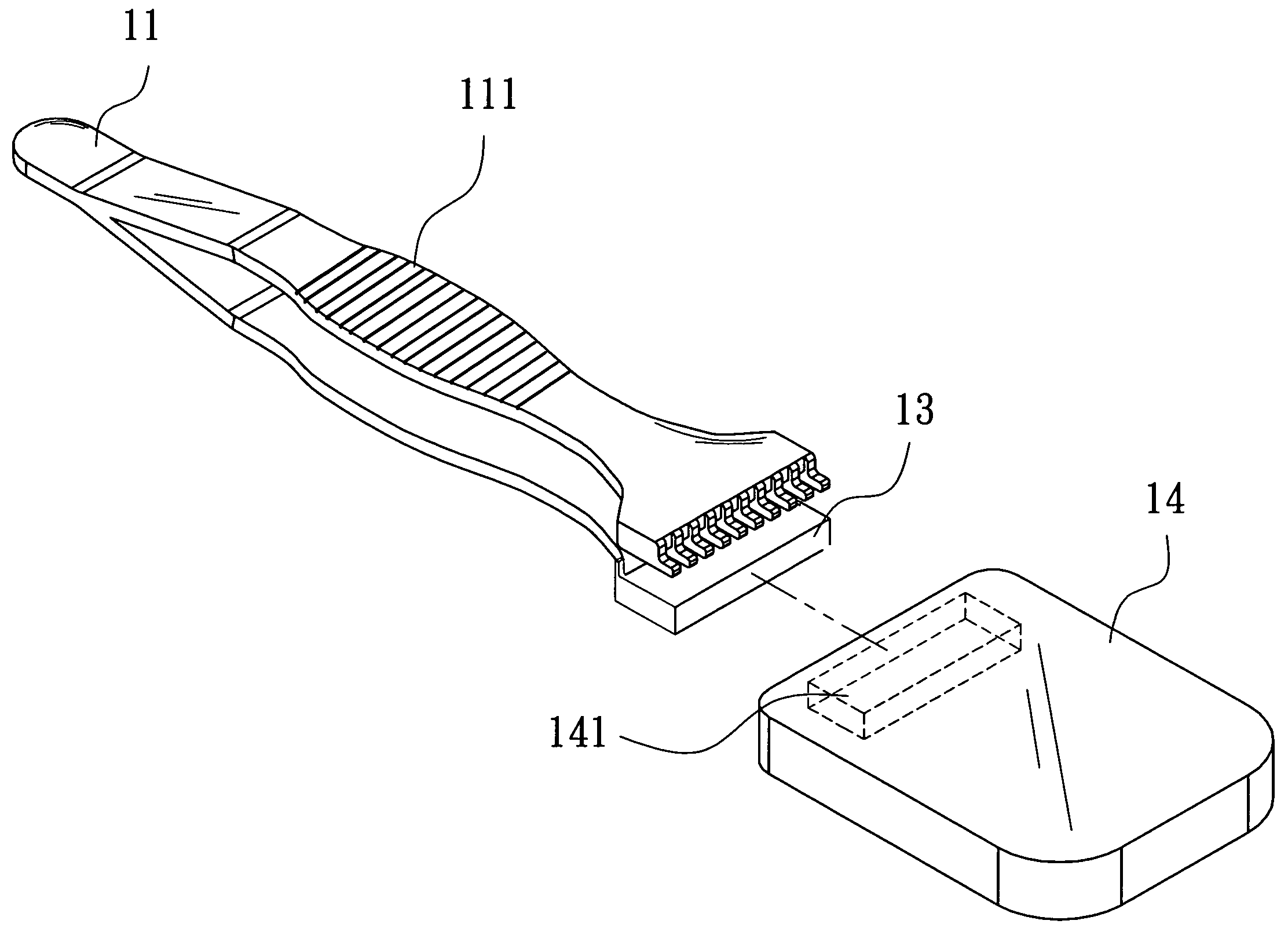
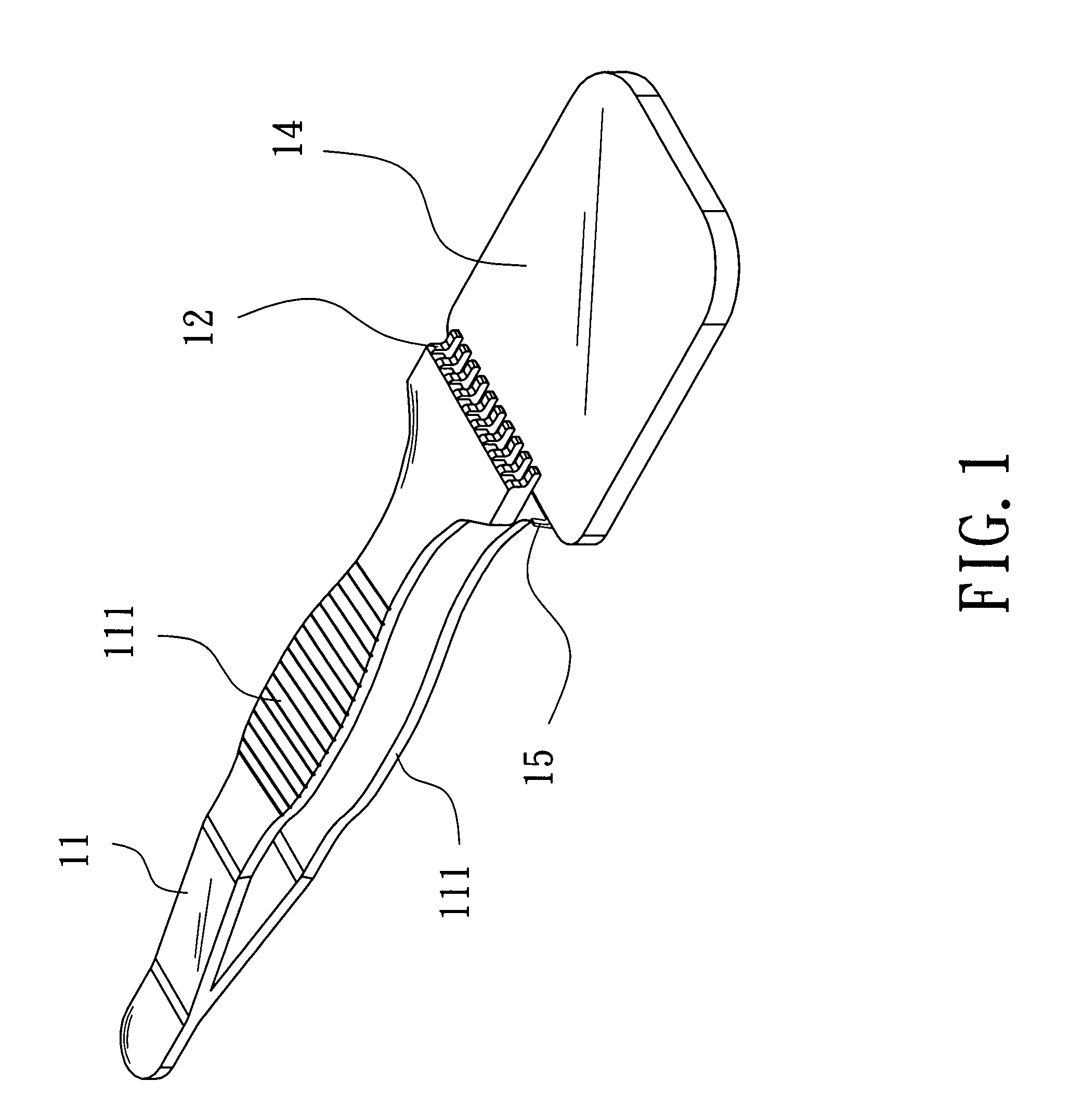
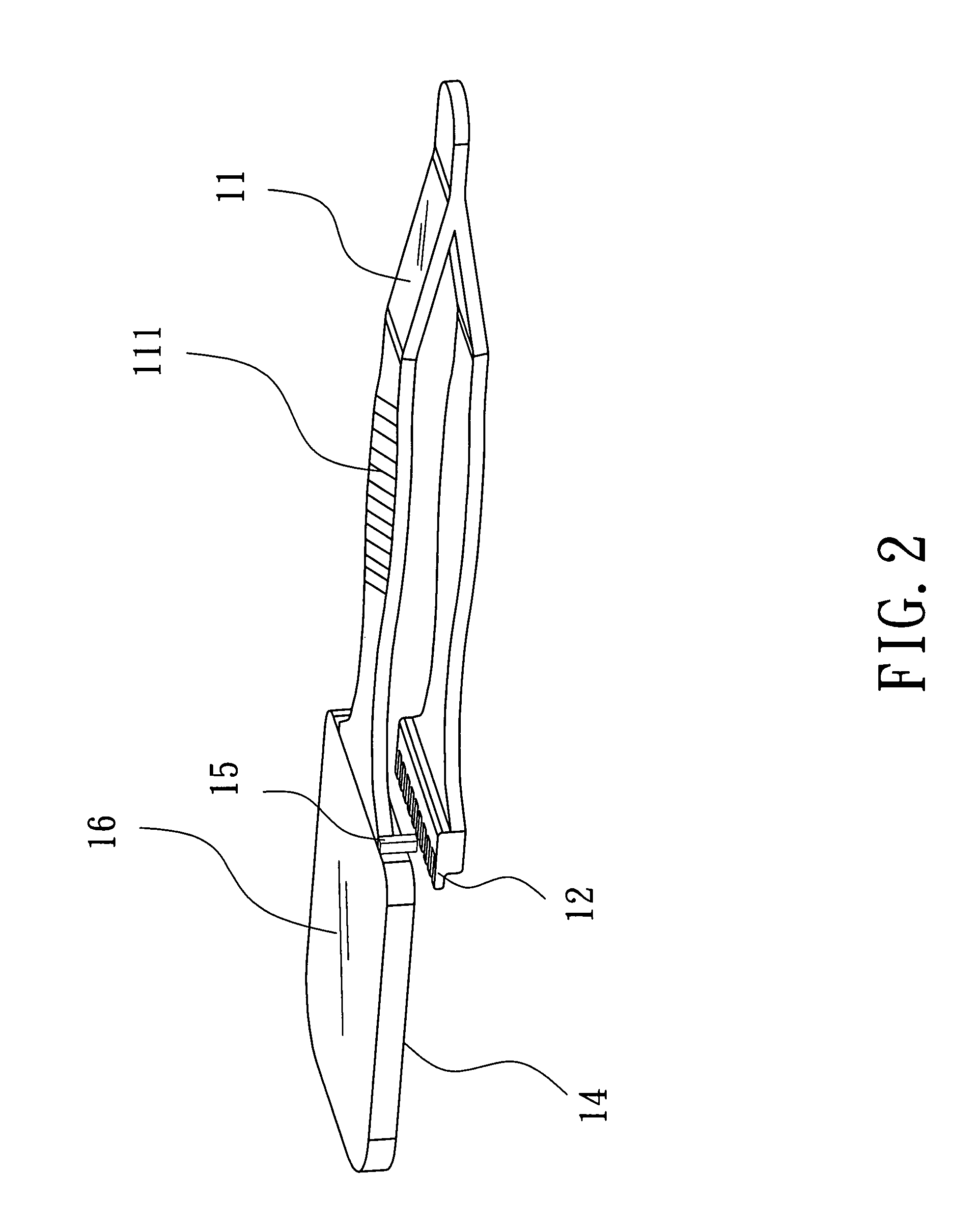
[0016]Please refer to FIG. 1 to FIG. 4, which are a first and a second perspective views and an explosive view showing a first preferred embodiment; and a view showing a supporting part of the first preferred embodiment according to the present invention. As shown in the figures, the present invention is a wafer clamp having a changeable supporting part, comprising a main body 11, which comprises a pressing part 111, a clamping part 12, a connecting part 13 and a hinderer 15; and a supporting part 14, where a wear resistance and a smoothness of a wafer (not shown in the figures) is improved with a replaceable supporting part 14.

[0017]The main body 11 is made of a metal plate into a whole one of a ‘V’ shape having the pressing part 111. The ‘V’ shape of the main body 11 has the clamping part 12 as an end and the connecting part 13 as the ot...


PUM


Abstract

A wafer clamp according to the present invention always firmly clamps a wafer. A supporting arm of the wafer clamp will be replaced with a different one according to the wafer size. Moreover, with a larger area of the supporting arm, a wear resistance and a smoothness of the wafer is improved. Besides, the wafer clamp stops the wafer from slipping. Hence, the present invention has a simple structure, a good practicality and a wide application.

Description

FIELD OF THE INVENTION[0001]The present invention relates to a wafer clamp; more particularly, relates to clamping a wafer having a various size and hindering the wafer from slipping.DESCRIPTION OF THE RELATED ART[0002]A smooth surface becomes more and more important to a high-quality wafer in these years. Yet, when the wafer is clamped by a wafer clamp, an unevenness on the surface where the wafer clamp clamps, or a small are a for clamping, the wafer may slip to fall on the ground and become damaged.[0003]Please refer to FIG. 10. A general wafer clamp 3 holds a wafer (not shown in the figure) with a clamping part 32 and a supporting part 33 by pressing a pressing part 31. However, both the clamping areas of the clamping part 32 and the supporting part 33 are too small, which may let the wafer 3 fall to the ground and be damaged. Besides, the wafer size nowadays is varied from 6 inches, 8 inches to 12 inches, and the general wafer clamp 3 does not fit those wafers having different ...

Claims


Application Information

Patent Timeline
Patent Type & Authority Patents(United States)
IPC IPC(8): B25B9/02
CPCH01L21/68707B25B9/02Y10S294/902
Inventor WU, CHIH-HUNGCHIU, HUNG-SHENGCHANG, KAI-SHENGCHU, KUAN-YU
Owner INST NUCLEAR ENERGY RES ROCAEC
Why Eureka
Try Eureka