Method and apparatus for measuring free induction decay signal and its application to composition analysis

a free induction decay and signal technology, applied in the field of nuclear magnetic resonance (“ nmr”) measurement of subsurface formations, can solve the problems of inhomogeneity, essentially unavoidable, and still some inhomogeneity in static magnetic field, so as to reduce the contribution of inhomogeneity

Active Publication Date: 2009-07-21
SCHLUMBERGER TECH CORP
View PDF13 Cites 7 Cited by
  • Summary
  • Abstract
  • Description
  • Claims
  • Application Information

AI Technical Summary

Benefits of technology

[0012]A method for analyzing materials in a sample volume according to another aspect of the invention includes inducing a static magnetic field in the sample volume. A radio frequency magnetic field is induced in the sample volume. The radio frequency magnetic field has parameters selected to reorient nuclear magnetic spins by a first selected angle from alignment with the static magnetic field. A reorienting radio frequency magnetic field is then induced in the sample volume. The reorienting field has parameters selected to reorient magnetic spins by a second selected angle and to minimize contribution of inhomogeneity in the static magnetic field to a free induction decay time. A free induction decay signal is detected from the sample volume. The inducing the reorienting radio frequency magnetic field and detecting the free induction decay signal are repeated until nuclear magnetic equilibrium is substantially attained.

Problems solved by technology

Notwithstanding that the above mentioned NMR apparatus induces a substantially homogeneous static magnetic field in the formations, there is still some inhomogeneity in the static magnetic field.
Such inhomogeneity is an essentially unavoidable result of “inside out” NMR apparatus such as well logging instruments, wherein the volume of investigation is entirely outside the apparatus.
Also it is difficult to design a magnet for application with well logging instruments having a magnetic field within a few parts per million (ppm) homogeneity within the investigated regions.
The length of time to acquire such sequences has the practical effect of limiting the speed at which the well logging instruments can be moved through the wellbore.

Method used


Image

  • Method and apparatus for measuring free induction decay signal and its application to composition analysis
  • Method and apparatus for measuring free induction decay signal and its application to composition analysis
  • Method and apparatus for measuring free induction decay signal and its application to composition analysis

Examples


Embodiment Construction

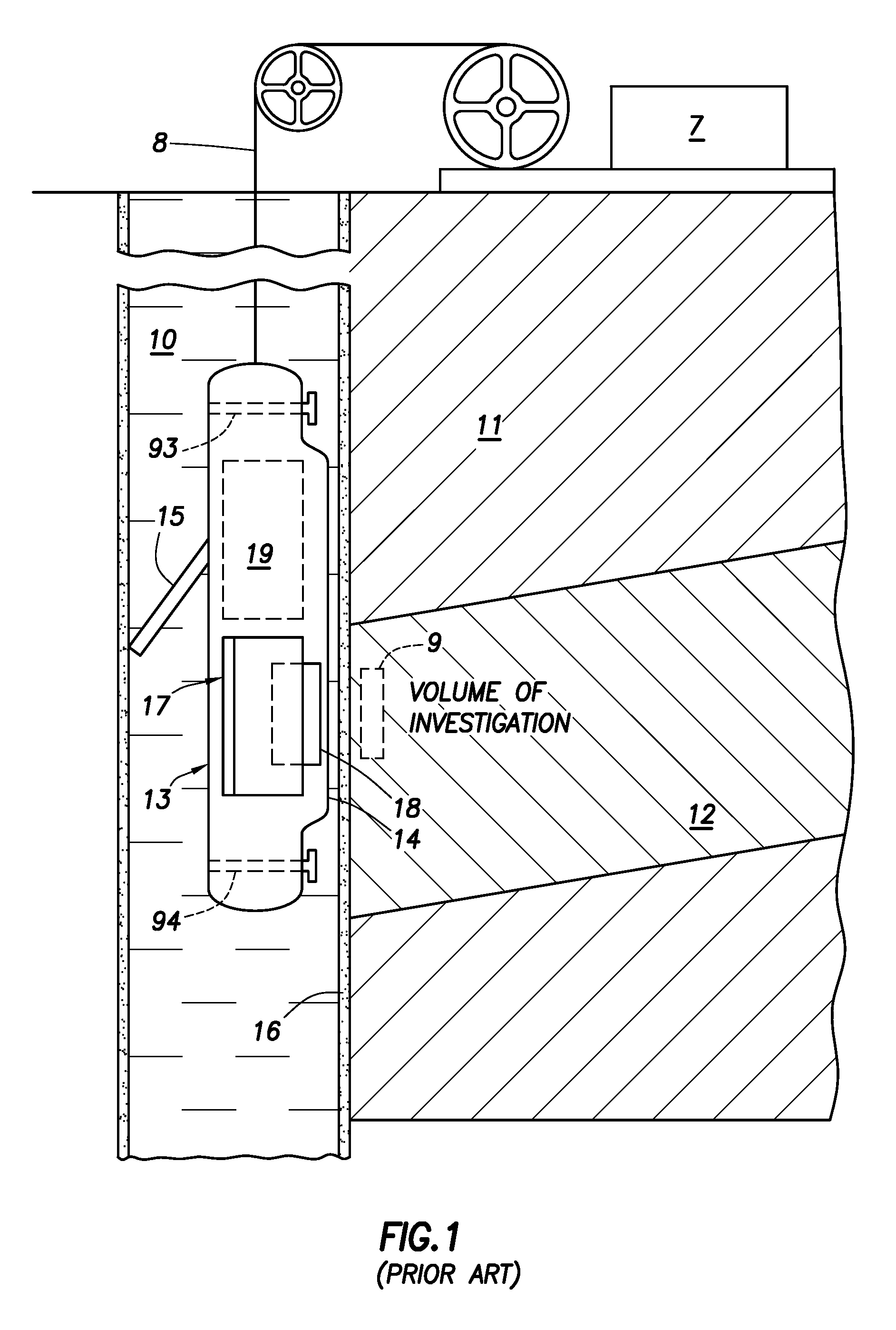
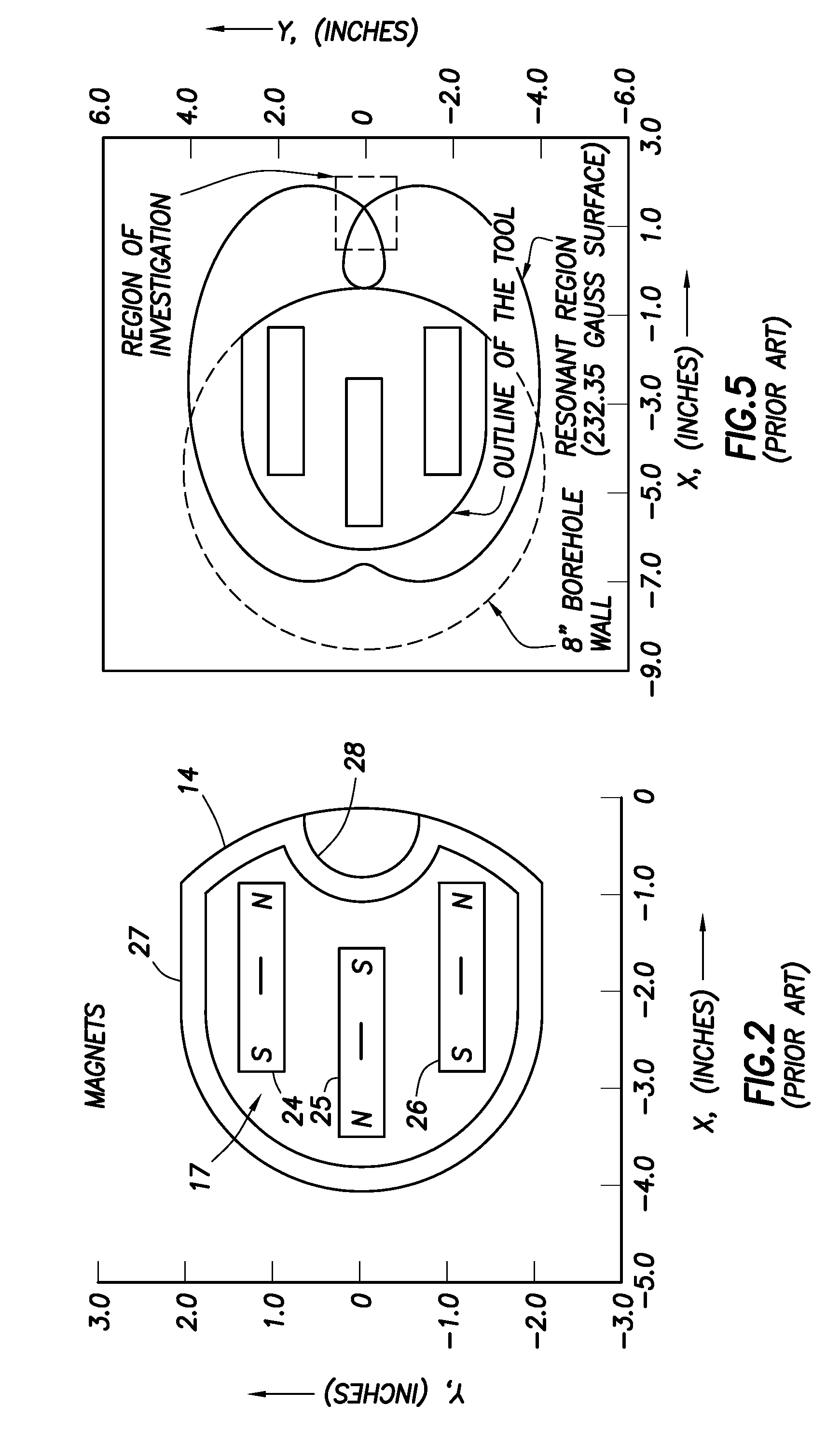
[0023]FIGS. 1 through 5, described below, are intended to show one example of a NMR well logging instrument that may be used in accordance with the invention. It is to be clearly understood that the various aspects of the present invention are not limited in scope to the implementations shown on such well logging instrument. In FIG. 1 a wellbore 10 is shown penetrating subsurface formations 11, 12, the characteristics of which are to be determined. Within the wellbore 10 there is shown a well logging instrument 13 connected with an armored electrical cable or “wireline”8 to surface equipment 7. The instrument 13 preferably has a face 14 shaped to contact the wellbore wall with minimal gaps or standoff. The instrument 13 also can have a retractable arm 15 which can be activated to press the body of the instrument 13 against the wellbore wall during operation of the instrument 13, wherein the face 14 is pressed against the wellbore wall.

[0024]Although the instrument 13 is shown in FIG...


PUM


Abstract

A method to obtain a free induction decay signal using includes inducing a static magnetic field in a sample volume. A radio frequency (RF) magnetic field is then induced in the sample volume. The RF magnetic field has parameters selected to minimize the contribution of inhomogeneity in the static magnetic field to a free induction decay time. The free induction decay signal is then detected from the sample volume. In one example, prior to inducing the RF magnetic field, a reorienting radio frequency magnetic field is induced in the sample volume to reorient magnetic spins by a first selected angle. The inducing the RF magnetic field in this example has parameters selected to reorient spins by a second angle. The inducing the RF magnetic field and detecting the free induction decay signal are repeated until nuclear magnetic equilibrium is substantially attained.

Description

CROSS-REFERENCE TO RELATED APPLICATIONS[0001]Not applicable.STATEMENT REGARDING FEDERALLY SPONSORED RESEARCH OR DEVELOPMENT[0002]Not applicable.BACKGROUND OF THE INVENTION[0003]1. Field of the Invention[0004]The invention relates generally to the field of nuclear magnetic resonance (“NMR”) measurement of subsurface formations penetrated by a wellbore. More specifically, the invention relates to methods and apparatus for measuring NMR free induction decay signals using wellbore deployed instruments, and the use of such free induction decay signals in determining NMR properties of the formation.[0005]2. Background Art[0006]NMR instruments used to make measurements of NMR properties of subsurface Earth formations, called “well logging” tools or instruments are moved along the interior of a wellbore drilled through such formations. NMR well logging devices known in the art include one described in U.S. Pat. No. 5,055,787 issued to Kleinberg et al. and assigned to the assignee of the pre...

Claims


Application Information

Patent Timeline
Patent Type & Authority Patents(United States)
IPC IPC(8): G01V3/00
CPCG01N24/081G01R33/3808G01V3/32G01R33/5602G01R33/383
Inventor GANESAN, KRISHNAMURTHY
Owner SCHLUMBERGER TECH CORP
Why Eureka
Try Eureka