Vise attachable fixture plate for use with CNC milling equipment

Inactive Publication Date: 2009-08-04
LOVAS STEPHEN R
View PDF23 Cites 18 Cited by
  • Summary
  • Abstract
  • Description
  • Claims
  • Application Information

AI Technical Summary

Benefits of technology

[0005]A fixture plate for use with a CNC milling machine having a support surface, a fixed jaw assembly together with a vise hook nut threadably? secured to a machine screw for moving the vise hook nut toward or away from the fixed jaw. The fixture plate is constructed of a generally rectangular block having a top surface, a bottom surface and a forward and rearward edge. The bottom surface of the block is positioned to rest on the support surface with the forward edge of the block resting against the fixed jaw. The

Problems solved by technology

This apparatus is inconvenient t

Method used


Image

  • Vise attachable fixture plate for use with CNC milling equipment
  • Vise attachable fixture plate for use with CNC milling equipment
  • Vise attachable fixture plate for use with CNC milling equipment

Examples


Embodiment Construction

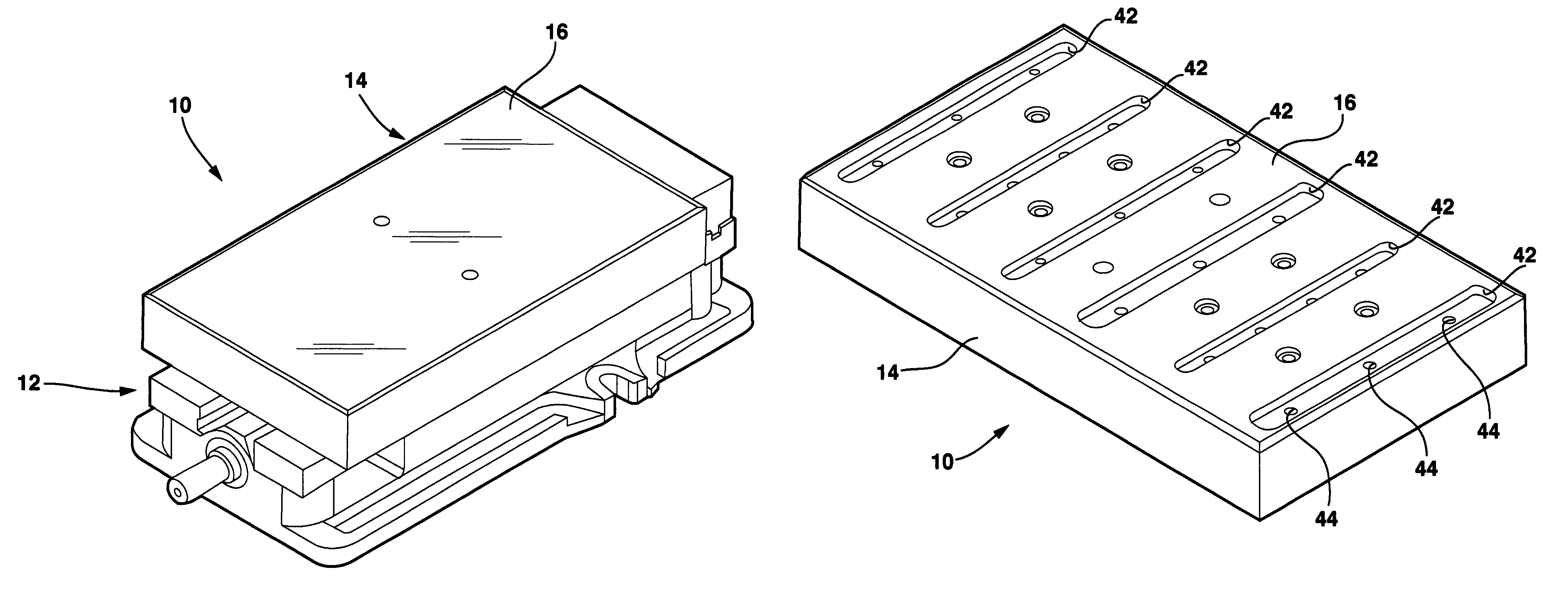
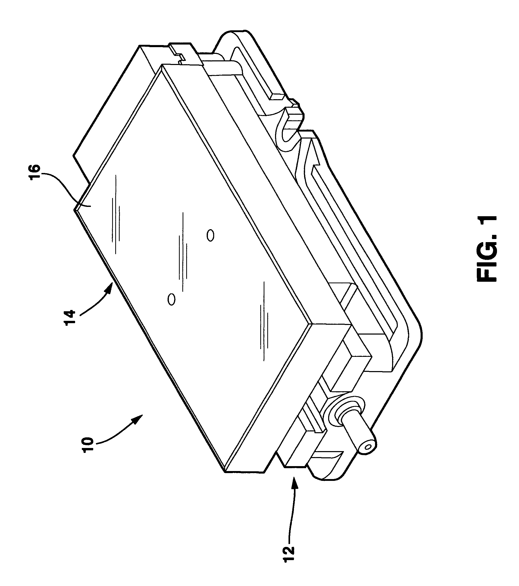
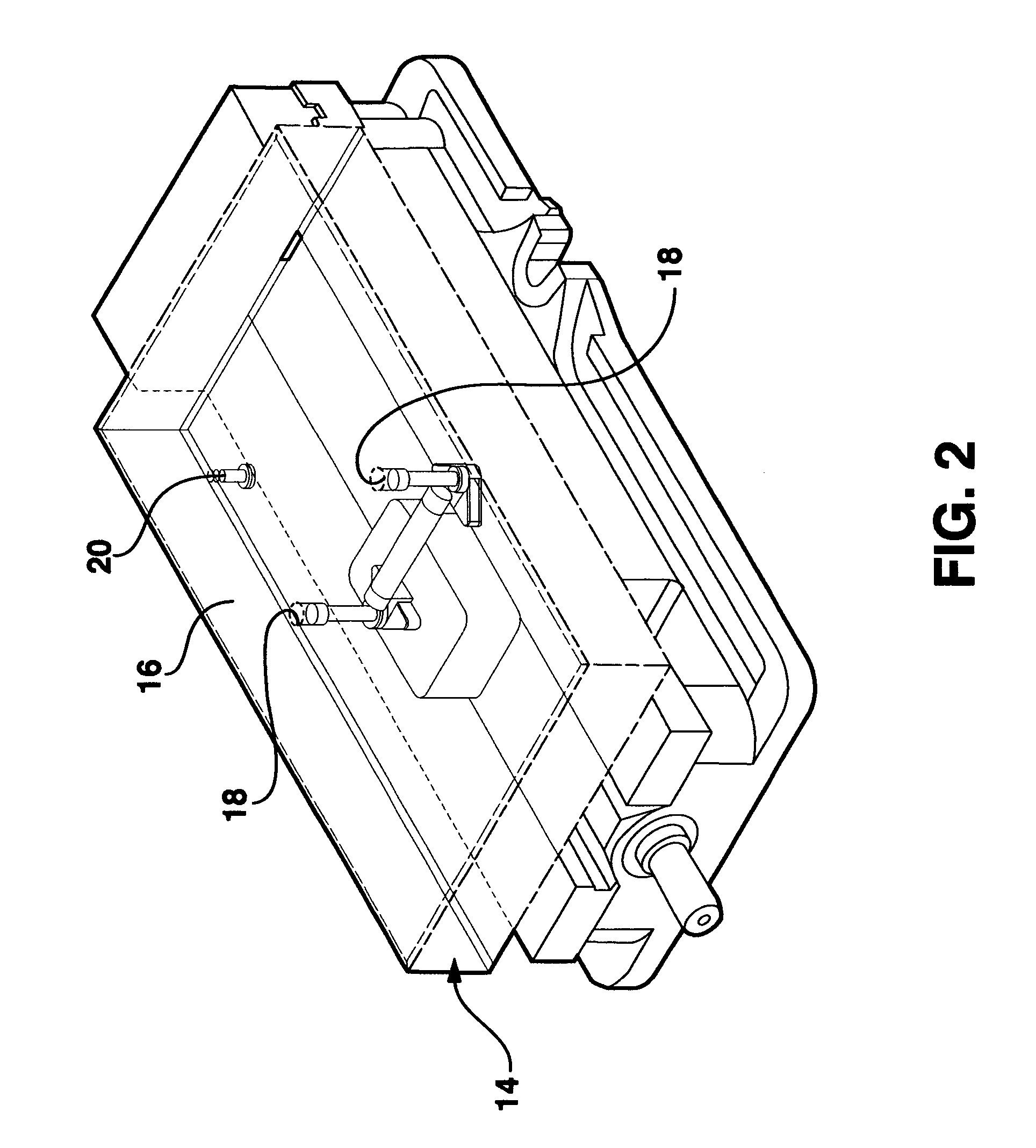
[0018]A vise attachable fixture plate 10 is shown in FIG. 1 mounted on a conventional vise 12 of a conventional CNC milling machine. The vise attachable fixture plate 10 is constructed of a generally rectangular block 14 which in a preferred embodiment is constructed of aluminum. The block 14 has a top surface 16 which is provided with a pair of stepped through holes 18 as shown in FIG. 2

[0019]A side view of the block 14 is shown in FIG. 4. An alignment stop 20 is mounted to the undersurface of the block 14 as shown in FIG. 4.

[0020]A bottom view of the block 14 is shown in FIG. 5. The block 14 includes a bottom surface 22 on which the alignment stop 20 is mounted as shown in FIG. 5. The bottom surface 22 is also provided with a clearance cavity 24 which opens into a pair of machined cavities 26 located on either side of the cavity 24 as shown in FIGS. 6 and 7.

[0021]A clamping pin 28 is positioned to have its opposite ends resting in a respective cavity 26 as shown in FIG. 6. A pair ...


PUM


Abstract

A fixture plate for use with a CNC milling machine. The fixture plate is constructed of a generally rectangular block having a top surface, a bottom surface and a forward edge. The bottom surface of the block is positioned to rest on the support surface with the forward edge of the block resting against the fixed jaw. The bottom surface of the block includes a cavity in which is mounted a clamping pin for coupling with the vise hook nut. When the machine screw is manipulated to move the mounting block toward the fixed jaw, the block is clamped to the vise between the fixed jaw and the vise hook nut. The top surface of the block is provided with grooves shaped to conform to the peripheral shape of each of the multiple workpieces. Clamping nuts, recessed in the grooves, are used for clamping the multiple workpieces to the block.

Description

[0001]This application claims the benefit of provisional application Ser. No. 60 / 811,694 filed Jun. 7, 2006.BACKGROUND OF INVENTION[0002]The present invention relates to a vise attachable fixture plate which can be used with conventional CNC milling equipment. The present invention allows users of the CNC milling equipment to machine multiple workpieces in a single setup.[0003]When machining a workpiece on conventional computer numerically controlled (“CNC”) machines the workpiece is typically held in place with a clamping member or vise. It is desirable to have the ability to mount as many workpieces at a single time to reduce the amount of machine set-up and tool-change time. An example of one such apparatus is described in U.S. Pat. No. 5,634,253 where multiple vises are mounted to the CNC machine. This apparatus is inconvenient to use and expensive to construct.[0004]The present invention solves the problem of mounting multiple workpieces on a CNC machine by providing a fixture ...

Claims


Application Information

Patent Timeline
IPC IPC(8): B25B11/00
CPCB25B1/2463B25B1/2452
Inventor LOVAS, STEPHEN R.
Owner LOVAS STEPHEN R
Why Eureka
Try Eureka