Check patentability & draft patents in minutes with Patsnap Eureka AI!

Vane pump

a technology of vane pump and cylinder head, which is applied in the direction of machines/engines, liquid fuel engines, positive displacement liquid engines, etc., can solve the problem of difficulty in forming a pin bore for standing the locating pin

Inactive Publication Date: 2009-08-18
KYB CORP
View PDF20 Cites 3 Cited by
  • Summary
  • Abstract
  • Description
  • Claims
  • Application Information

AI Technical Summary

Benefits of technology

This design enhances the assembly process and reduces operational fluctuations by ensuring accurate positioning of the cam ring and side plates, improving the pump's sealing and operational efficiency.

Problems solved by technology

Therefore, there is a problem with difficulty to form a pin bore for standing the locating pin.

Method used


Image

  • Vane pump
  • Vane pump
  • Vane pump

Examples


Embodiment Construction

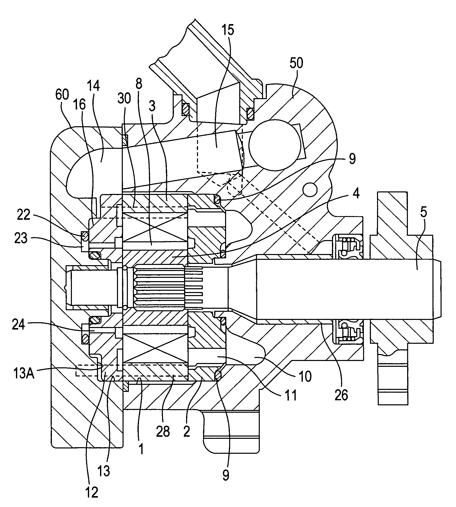
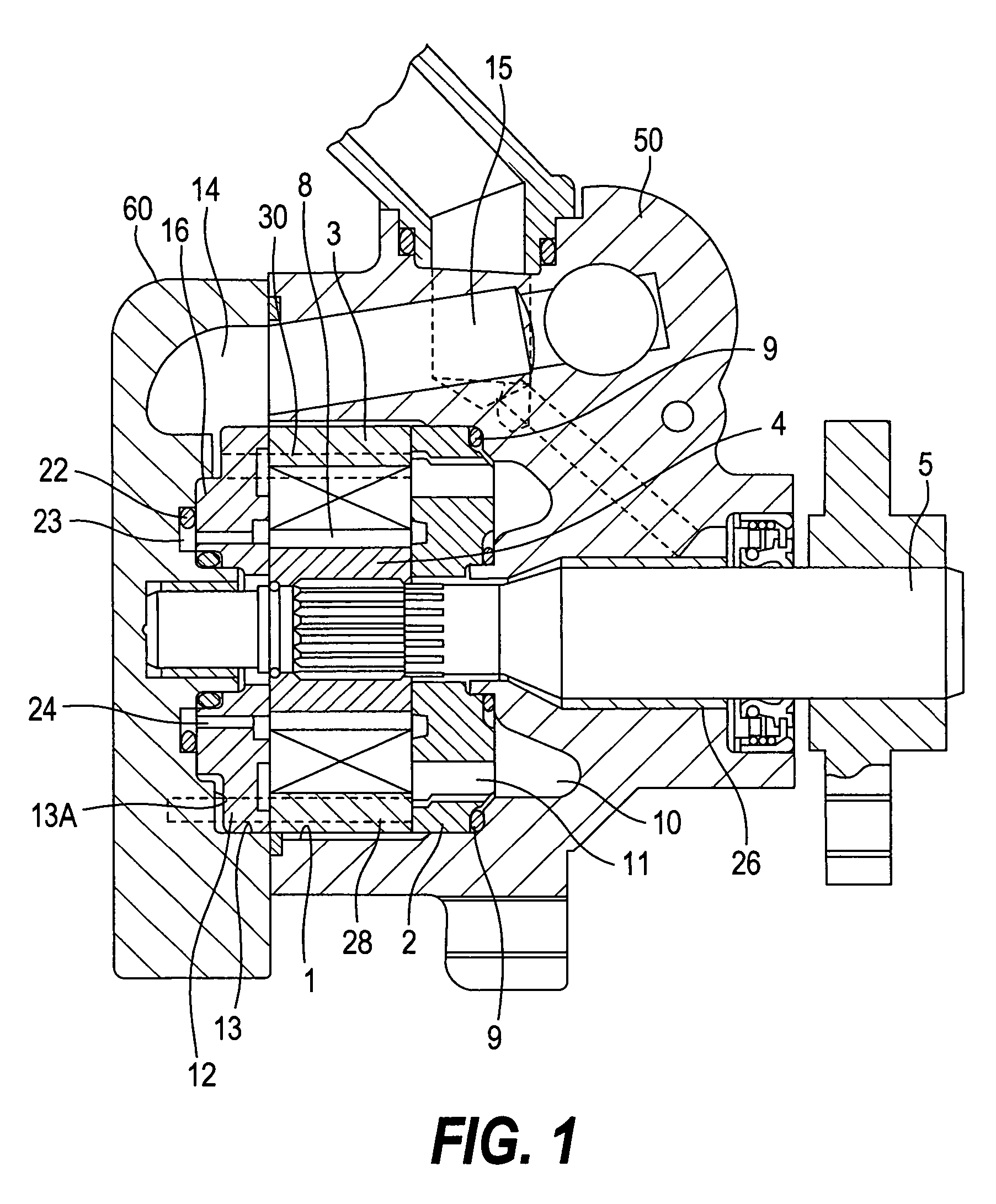
[0019]The present invention will be explained with reference to the drawings as below. As shown in FIG. 1, a present embodiment is provided with a body 50 defining a body bore 1 therein and a cover 60 for covering the body bore 1. A front-side side plate 2 and a cam ring 3 are assembled in the body bore 1. A cross section of the body bore 1, as shown in FIG. 3, is not a complete circle. The cam ring 3 incorporates a rotor 4 therein. The rotor 4 rotates together with a rotating shaft 5 and can move in an axial direction of the rotating shaft 5. Vane grooves 6 for assembling vanes are formed radially and at an equal interval in a rotor 4 and the vanes 7 are incorporated into the vane grooves 6 so that the vanes 7 freely move in and out. The vane groove 6 defines a backpressure chamber 8 at the base end and a discharge pressure is introduced into this back pressure chamber 8.

[0020]Accordingly, when the rotor 4 rotates with the rotating shaft 5, the vanes 7 move in and out along the tra...


PUM


Abstract

A vane pump of the present invention is provided with a bearing convex portion (20) disposed in such a way to be raised from the bottom of a concave portion (13) of a cover (60) to form a bearing hole (25) and fitted into a central bore (27) of a first side plate (12), and a first locating pin (28) standing at the bottom of the concave portion (13), penetrating through the first side plate (12) and inserted into a cam ring (3).

Description

[0001]The present invention claims priority to Japanese patent application No. 2004-293351, filed on Oct. 6, 2004, which is incorporated by reference in its entirety.FIELD OF THE INVENTION[0002]The present invention relates to a vane pump with a locating pin disposed in a cover.BACKGROUND OF THE INVENTION[0003]JP62-271982A published by the Japan Patent Office has disclosed a vane pump as mentioned below. The vane pump incorporates a cam ring into a body bore disposed in a body and also incorporates a rotor into the cam ring. A plurality of vanes is disposed inside the cam ring in such a way to freely move in the rotor and out of the rotor. The rotor is connected to a drive shaft and rotates with rotation of the drive shaft, as well as moves in and out the vanes disposed in the rotor along an inside face of the cam ring. In the process the rotor rotates, chambers defined by the neighboring vanes contract and expand. When the chamber expands, the vane pump is at the suction stroke, an...

Claims


Application Information

Patent Timeline
Patent Type & Authority Patents(United States)
IPC IPC(8): F04B49/00
CPCF01C21/108F04C2/3446F04C2240/80F04C2230/603
Inventor IDE, NORIKAZUNAGASAKA, RYOUICHIYAKABE, SHINJI
Owner KYB CORP
Features
  • R&D
  • Intellectual Property
  • Life Sciences
  • Materials
  • Tech Scout
  • Unparalleled Data Quality
  • Higher Quality Content
  • 60% Fewer Hallucinations
Learn More