
Electrical connector with improved contacts arrangement

a technology of contacts arrangement and electric connectors, applied in the direction of coupling device connections, electrical discharge lamps, coupling device details, etc., can solve the problems of limited use of express cards, insufficient usb transmission rate, and insufficient use of non-usb protocols

Active Publication Date: 2009-08-25
HON HAI PRECISION IND CO LTD
View PDF8 Cites 32 Cited by
  • Summary
  • Abstract
  • Description
  • Claims
  • Application Information

AI Technical Summary

Benefits of technology

The present invention relates to an electrical connector with a first interface and a second interface arranged side by side. The connector has a first contact group held in the first interface and a second contact group held in the insulative housing and extending into the second interface. The first contact group has a plurality of first contacts and a plurality of second contacts with different heights along a thickness direction of the first tongue plate. The technical effect of this invention is to provide an electrical connector with improved contacting performance and reliability.

Problems solved by technology

However, under a circumstance transmitting an audio or video file, which is always up to hundreds MB, even to 1 or 2 GB, currently transmission rate of USB is not sufficient.
However, these non-USB protocols are not used as broadly as USB protocols.
For example, while the PCI Express is useful for its higher possible data rates, a 26-pin connectors and wider card-like form factor limit the use of Express Cards.

Method used


Image

  • Electrical connector with improved contacts arrangement
  • Electrical connector with improved contacts arrangement
  • Electrical connector with improved contacts arrangement

Examples


first embodiment

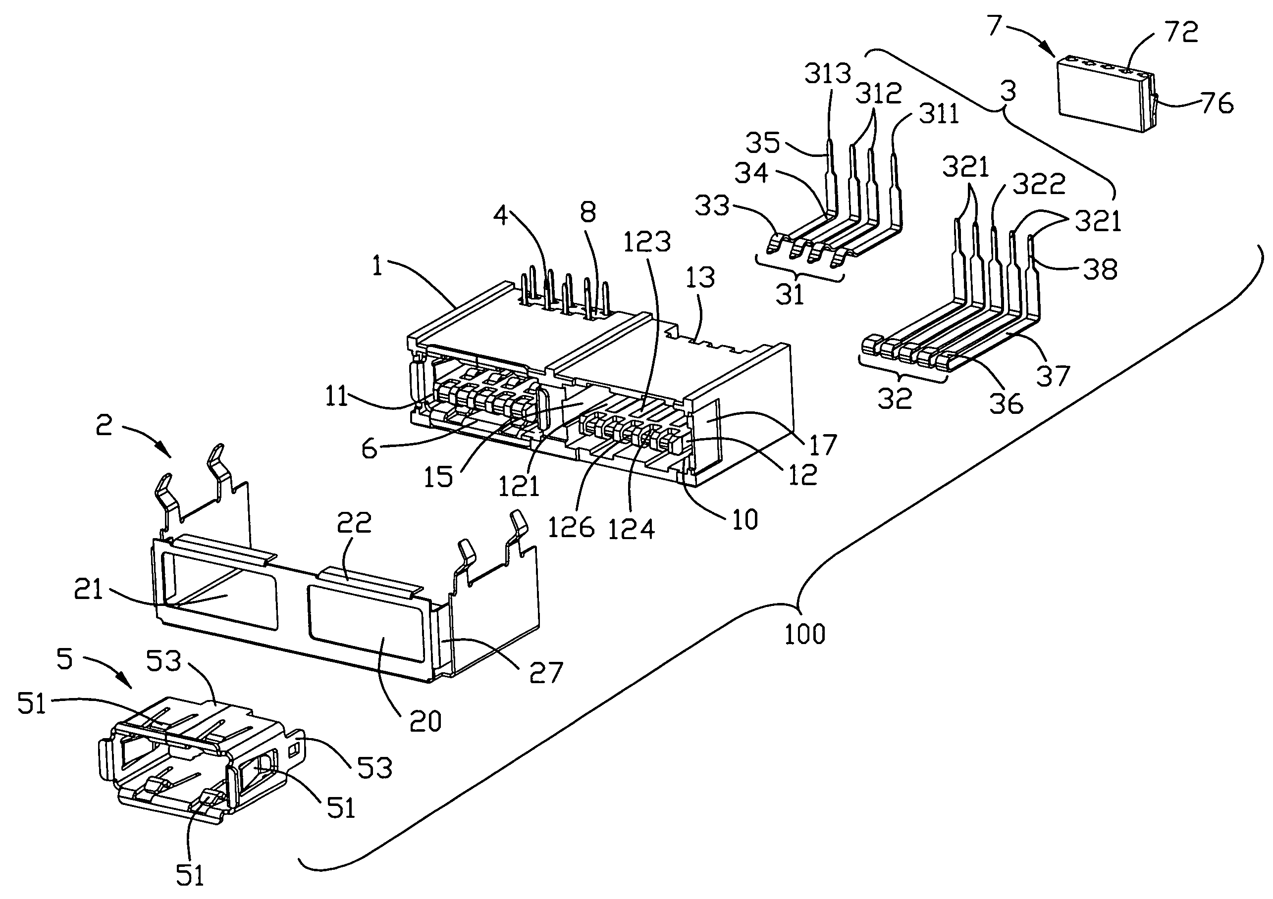
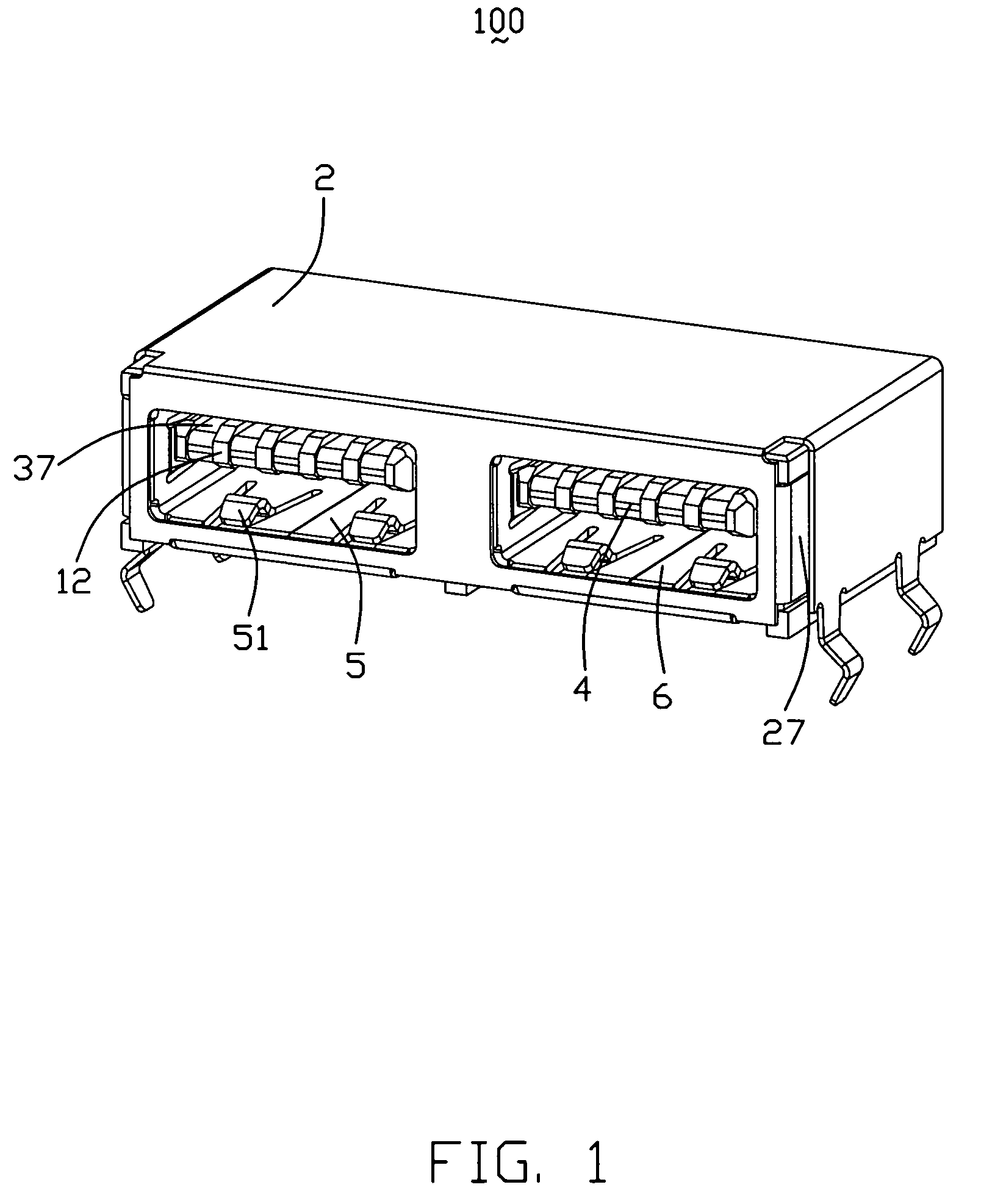
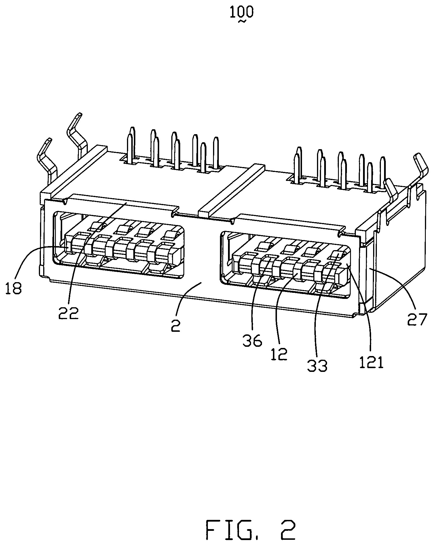
[0022]Referring to FIGS. 3-5, an electrical connector 100 according to the present invention, comprises an insulative housing 1, a first contact group 3 and a second contact group 4 held in the insulative housing 1, a first inner shell 5, a second inner shell 6, a first spacer 7 and a second spacer 8 assembled to the insulative housing 1, and an outer shell 2 enclosing the insulative housing 1.

[0023]Referring to FIG. 3-5, the insulative housing 1 integrally formed with a first interface 10 and a second interface 11 located at a lateral side of the first interface 10. The structure of the first interface 10 and the second interface 11 are the same, so now taking the first interface 10 for example. The first interface 10 comprises a receiving chamber 15 and a first tongue plate 12 extending therein for supporting the first contact group 3. The first tongue plate 12 forms an upper side 122 and a lower side 121 opposite to the upper side 122. A plurality of first grooves 123 arranged in...

second embodiment

[0030]Referring to FIG. 6, in present invention, the electrical connector 100 can have no first inner shell 5 and second inner shell 6.

[0031]In the first embodiment of the present invention, the first tongue plate 12 is received in a lower portion of the receiving chamber 15, the first contacting portions 33 and the second contacting portions 36 are located on the lower side 121 of the first tongue plate 12. Referring to FIG. 7, in a third embodiment of the present invention, the first tongue plate 12′ could be received in an upper portion of the receiving chamber 15′, the first contacting portions 33′ and the second contacting portions 36′ are located on the upper side 122′ of the first tongue plate 12′.


PUM


Abstract

An electrical connector (100) includes a first interface (10) having a first tongue plate (12) extending therein, a second interface (11) disposed on a side of the first interface, a first contact group (3) held in the first tongue plate, and a second contact group (4) extending into the second interface. The first contact group includes a set of first contacts (31) each having a first resilient contacting portion (33) and a set of second contacts (32) each having a second stiff contacting portion (36). The first contacting portion (33) and the second contacting portion (36) are essentially located on a same side of the first tongue plate (12).

Description

BACKGROUND OF THE INVENTION[0001]1. Field of the Invention[0002]The present invention generally relates to an electrical connector and more particularly to an electrical connector adapted for mating with a standard Universal Serial Bus (USB) plug.[0003]2. Description of Related Art[0004]Personal computers (PC) are used in a variety of ways for providing input and output. Universal Serial Bus (USB) is a serial bus standard to the PC architecture with a focus on computer telephony interface, consumer and productivity applications. The design of USB is standardized by the USB Implementers Forum (USB-IF), an industry standard body incorporating leading companies from the computer and electronic industries. USB can connect peripherals such as mouse devices, keyboards, PDAs, gamepads and joysticks, scanners, digital cameras, printers, external storage, networking components, etc. For many devices such as scanners and digital cameras, USB has become the standard connection method.[0005]As ...

Claims


Application Information

Patent Timeline
Patent Type & Authority Patents(United States)
IPC IPC(8): H01R24/00
CPCH01R13/514
Inventor HE, JIA-YONGZHENG, QI-SHENG
Owner HON HAI PRECISION IND CO LTD
Learn More