Downhole tool with C-ring closure seat and method

a technology of c-ring closure and tool seat, which is applied in the direction of sealing/packing, fluid removal, borehole/well accessories, etc., can solve the problems of ball seat failure, seat design with collet fingers also failing to seal properly, and not being able to allow

Active Publication Date: 2009-09-01
DRIL QUIP
View PDF15 Cites 37 Cited by
  • Summary
  • Abstract
  • Description
  • Claims
  • Application Information

AI Technical Summary

Benefits of technology

[0010]In another embodiment, the liner hanger assembly as discussed above is provided with an expandable C-ring and a seal for sealing with the closure member when positioned on the C-ring. A shear pin release member need not be provided, and instead the operator may selectively pick up the work string, thereby lifting a sleeve-shaped retainer which holds in pins which serve as stops to hold the C-ring in an axially intermediate position. Upward movement of the retainer thus allows the C-ring to expand to its expanded position within an enlarged lower diameter cavity, thereby releasing the ball. A similar assembly may be used in other downhole tools to activate tool components in response to a varying pressure level within the tool, including one or more production packers, a downhole setting tool, or a multilateral tool.

Problems solved by technology

Various problems with this design may occur when the collet fingers fail to properly seal and do not allow for pressure to build up so that the collet fingers can move downward and let the ball drop through the seat.
Another problem with this type of expandable ball seat is that wellbore fluids pass by the collet fingers, thereby eroding the fingers and tending to cause the ball seat to fail.
A ball seat design with collet fingers may also fail to seal properly and not allow for the pressure to build up so that the collets release to pass the ball through the seat.
This design is complicated with many parts and components that may cause failure.
Quality control for the expandable area may be difficult, and the expandable ball seat may not yield when intended.
Expandable ball seats thus do not always reliably release the ball at a preselected pressure.
In some situations, pressure used to release the ball from the upper seat may generate a full force sufficient to pass the ball through the lower seat, which then makes it impractical to further operate the tool.
High pressure applied to the ball releasing system may also damage the tool or damage the skin of the downhole formation.
The design as disclosed in this patent is complicated, and one has to equalize the pressure across the ball seat before mechanically manipulating the drill string to release the ball.

Method used


Image

  • Downhole tool with C-ring closure seat and method
  • Downhole tool with C-ring closure seat and method
  • Downhole tool with C-ring closure seat and method

Examples


Embodiment Construction

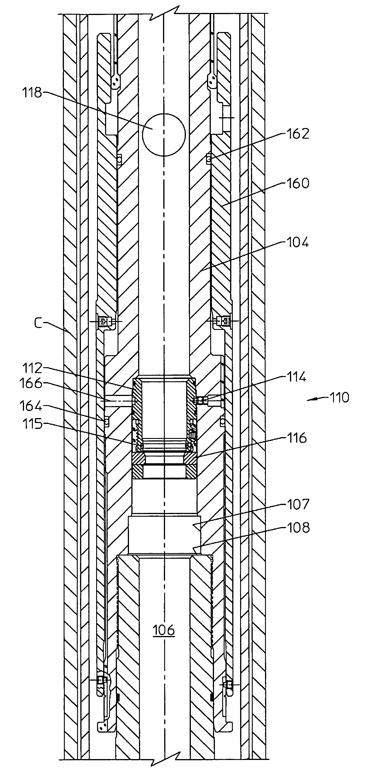
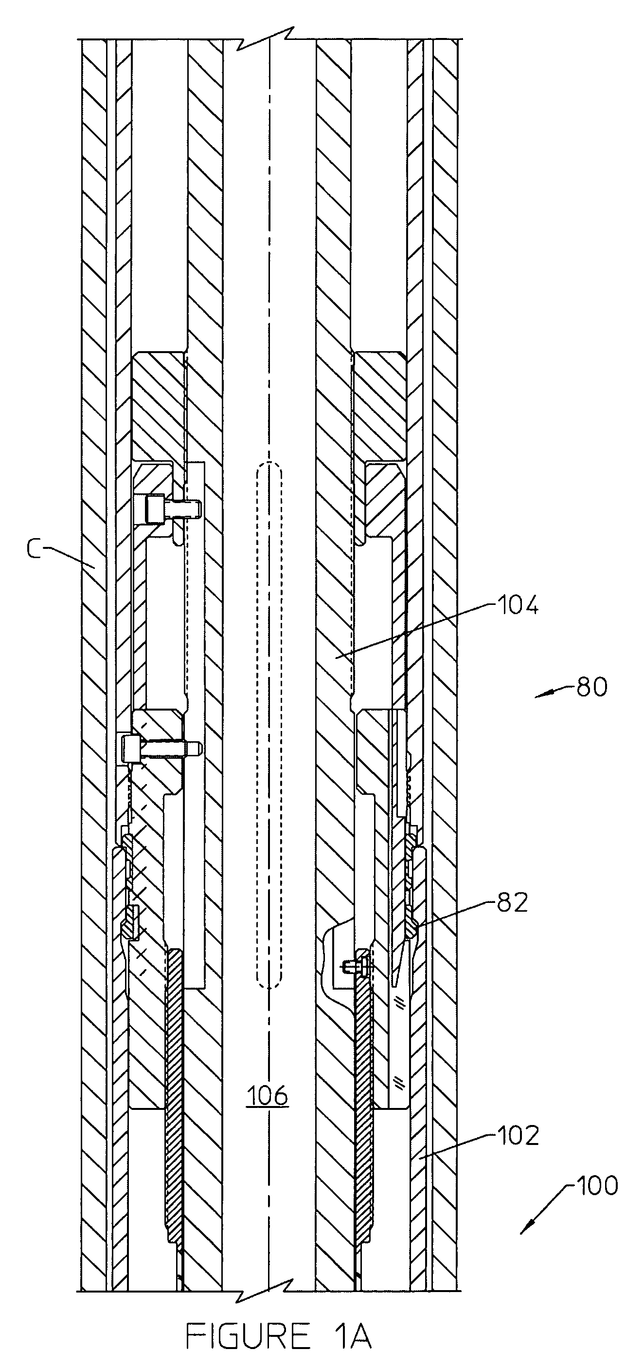
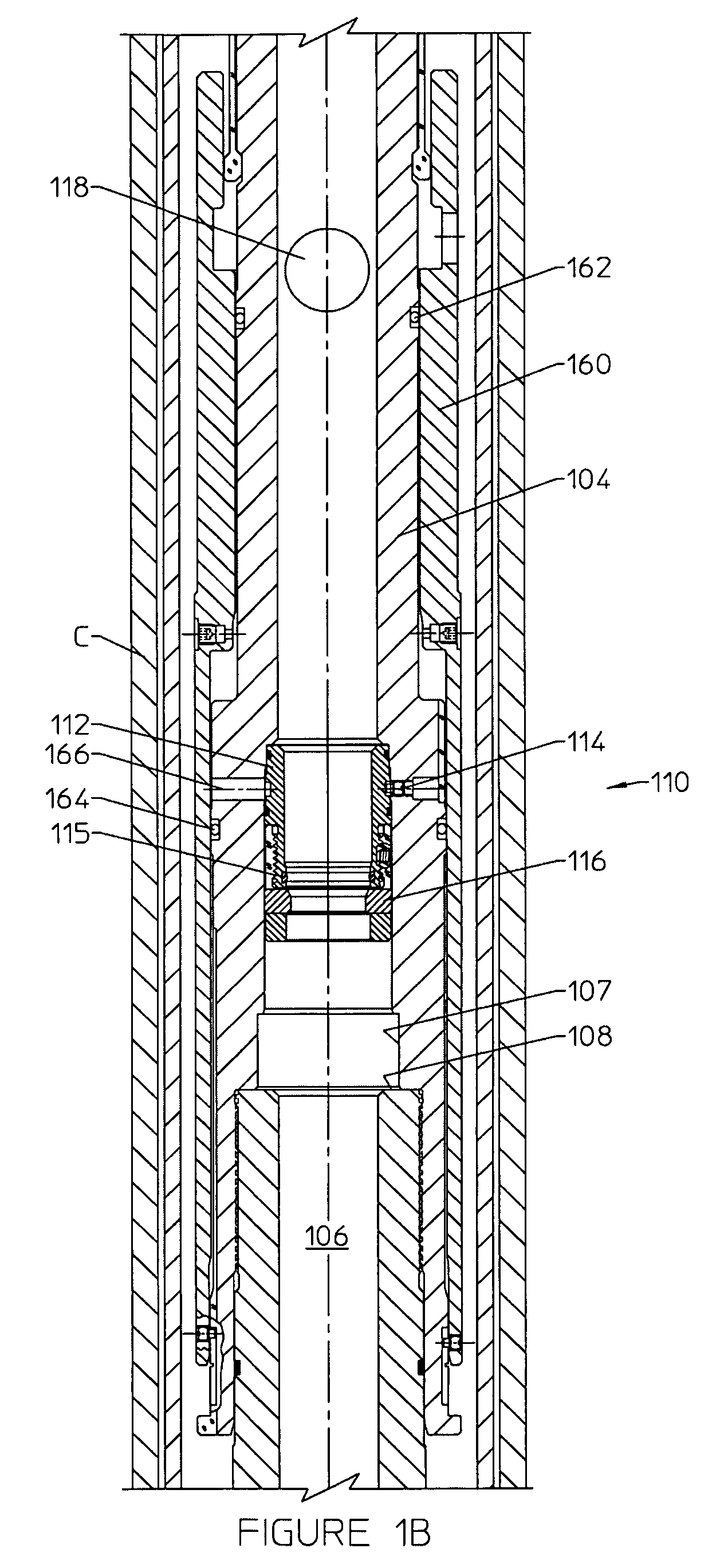
[0021]FIG. 1, which consists of FIGS. 1A-1G, illustrates one embodiment of a liner hanger tool 100 with two C-ring seat subassemblies each for seating with a closure member in a liner hanger application. An upper C-ring seat subassembly 110 is shown in FIG. 1B, and a lower C-ring seat subassembly 170 is shown in FIG. 1D. Other than components associated with seating and releasing the closure member, the primary components of the liner hanger running tool 100 as shown in FIG. 1 include a running tool tieback locking mechanism 80 (FIG. 1A), a slip release assembly operatively responsive to the upper C-ring seat assembly 110, packer setting lugs 180 (FIG. 1C), a liner hanger release assembly operatively responsive to the lower C-ring seat assembly (FIG. 1D), a cementing bushing 130 (FIG. 1E), and a ball diverter 140 and plug release assembly 150 (FIG. 1G). FIG. 1E illustrates the packer 122 and FIG. 1F illustrates the slip assembly 120, which are not part of the running tool retrieved ...


PUM


Abstract

A downhole tool 100 includes a closure seat 116, 176 for seating with a closure, such as a ball. Shear pins or other connectors temporarily limit axial movement of the closure seat which is initially housed within a restricted diameter portion of the central throughbore in the tool body. The closure seat may be lowered to engage a stop 108, 157, thereby positioning the seat within an enlarged diameter bore portion of the tool and allowing radial expansion of a closure seat to release the ball.

Description

CROSS REFERENCE TO RELATED APPLICATIONS[0001]This application claims priority from U.S. Patent Application Ser. No. 60 / 785,653, filed Mar. 24, 2006 for a DOWNHOLE TOOL WITH C-RING CLOSURE SEAT, which is incorporated herein in its entirety for all purposes.FIELD OF THE INVENTION[0002]The present invention relates to downhole tools adapted for receiving a ball or other closure member to provide for the increase in fluid pressure above the seated closure within the tool, thereby actuating components of the tool. More particularly, the present invention relates to a liner hanger assembly for hanging a liner in a well, and to a relatively simple and highly reliable closure seat which allows a ball to reliably pass by the seat after desired tool operations are complete.BACKGROUND OF THE INVENTION[0003]Various types of downhole tools are adapted for utilizing an increase in fluid pressure to actuate components of the tool. Packer setting tools, multilateral tools and liner hangers are plus...

Claims


Application Information

Patent Timeline
Patent Type & Authority Patents(United States)
IPC IPC(8): E21B33/128
CPCE21B23/04E21B43/10E21B23/06E21B23/0413E21B34/14
Inventor REIMERT, LARRY E.WALKER, JAMES M.
Owner DRIL QUIP
Why Eureka
Try Eureka