Surgical ligation clip and method for use thereof

a technology of ligation clips and surgical instruments, applied in the field of surgical ligation clips, can solve the problems of variable force applied by the ligation clips to the vessel, difficulty in removal or repositioning, and inconsistent force applied by the ligation clips, and achieve the effect of low profil

Inactive Publication Date: 2009-09-01
MICROLINE SURGICAL INC +1
View PDF222 Cites 298 Cited by
  • Summary
  • Abstract
  • Description
  • Claims
  • Application Information

AI Technical Summary

Problems solved by technology

Such crushing actions, of course, permanently deform the clips, making them difficult to remove or re-position.
Prior art surgical ligation clips have several inherent problems.
For example, the force applied by the clip to the vessel can be variable and inconsistent from one clip to the next, because of the variation in crushing force applied to the clip by the user.
Further, prior art clips have a tendency to slip off the end of the blood vessel stub (i.e., parallel to the axis of the vessel) to which it has been applied, because of the low coefficient of friction associated with the clip, and lack of adequate restraining force provided by the clip.
A related problem found in the prior art is the fact that the ligating or restraining force offered by the crushed clip varies along the length of the clip, decreasing toward the open end.
Thus, the section of the vessel near the open end of the clip can be inadequately ligated.
This does not lend itself to clip applier designs that will pass through small 5 mm trocars.
Accordingly, the clip applier mechanism of the prior art must be relatively large and cumbersome.
This is a particular problem in laparoscopic procedures, during which both the clip and clip applier must be inserted through a trocar placed through the patient's external tissues and into the surgical field.
Unfortunately, several problems are encountered in applying this novel pre-formed, spring-action ligating clip onto a vessel through a 5 mm trocar port.
First, the nominal 5 mm cross section of the clip that is inserted through the trocar places severe design restrictions on any applier mechanism.

Method used


Image

  • Surgical ligation clip and method for use thereof
  • Surgical ligation clip and method for use thereof
  • Surgical ligation clip and method for use thereof

Examples


Embodiment Construction

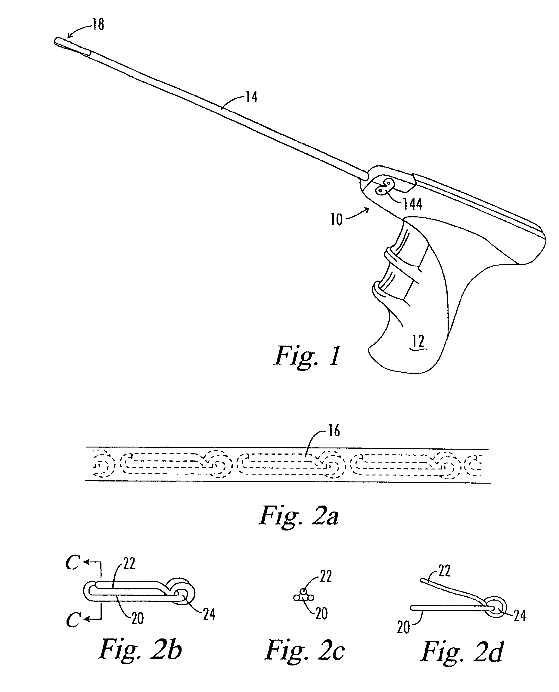
[0037]Referring now to FIG. 1, there is shown generally the preferred embodiment of the present clip applier. The device is indicated generally by the numeral 10. The device 10 includes the pistol grip 12 and an applicator sleeve 14. The applicator sleeve 14 contains a number of ligation clips 16 all in stacked relation and held in position in the manner hereinafter described. The ligation clips 16 are stacked generally in the trunk portion of the applicator sleeve 14 and extend from the end of the sleeve 14 that is connected to the pistol grip 12 toward the distal end 18 of the device 10.

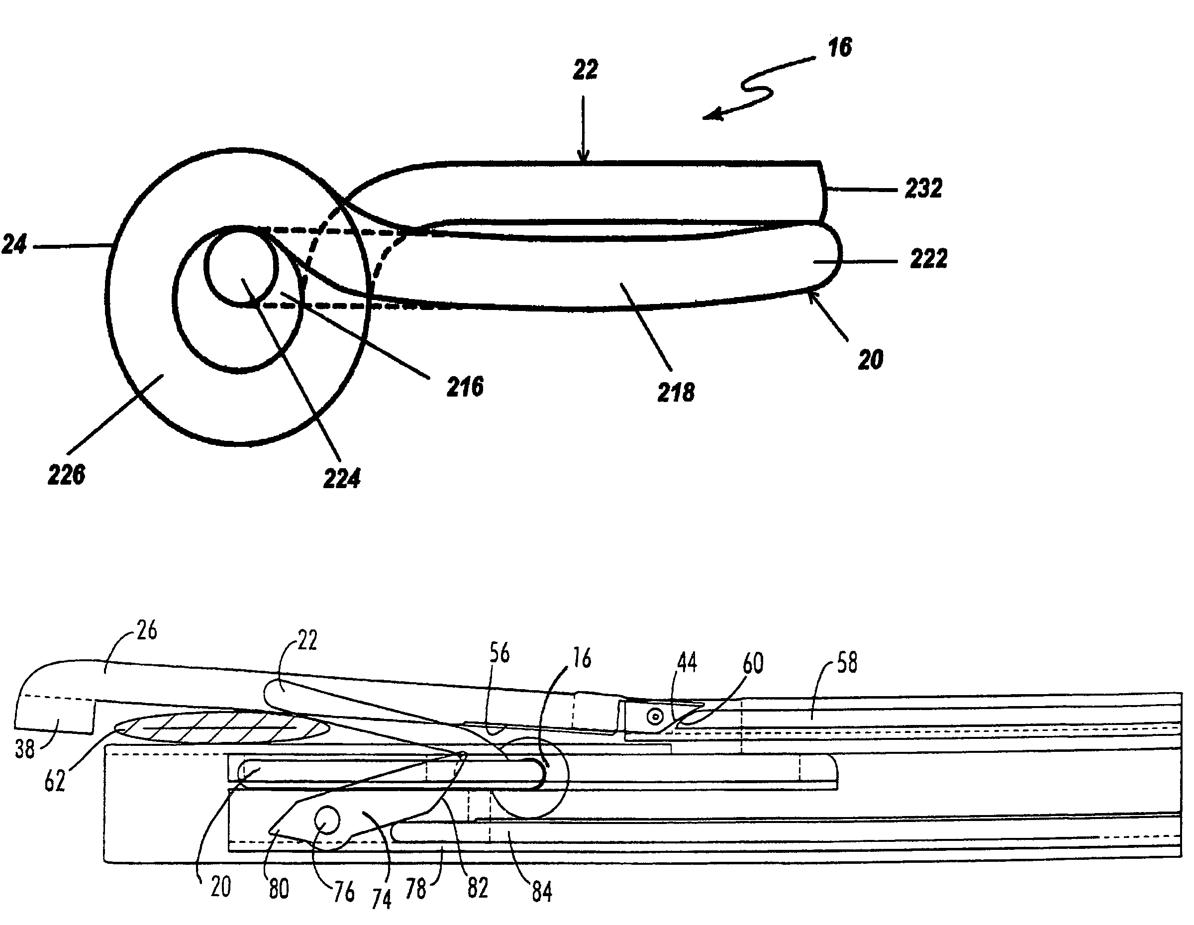
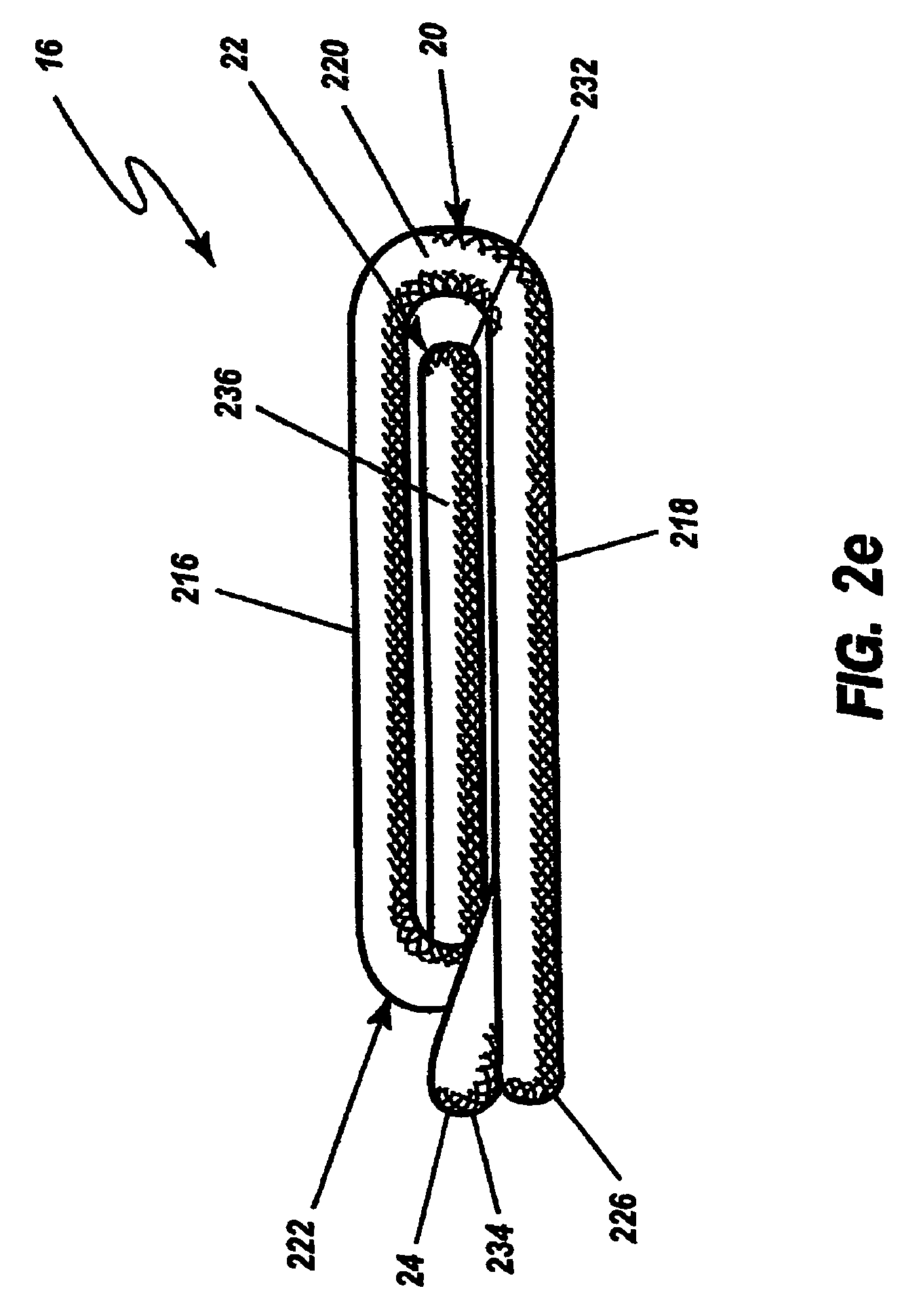
[0038]FIG. 2b shows the shape and construction of a typical ligation (or surgical) clip 16 which device 10 of the present invention is designed to apply during surgical procedures. Ligation clip 16, additional preferred embodiments of which are shown in FIGS. 2e-2h and FIGS. 2i and 2j, is formed generally of a resilient, continuous, wire type material such as titanium or stainless steel, preferably...


PUM


Abstract

The clip applier of the current invention solves the problems of prior art tools by incorporating a pre-clamp mechanism, the function of which is to pre-clamp the vessel to be ligated to a dimension such that the center leg of the spring of the ligation clip need be lifted only slightly. In this manner the spring clip can be slid over the smaller pre-clamped dimension. This insures that the clip spring material will remain within its elastic limit while allowing the tool to maintain a low profile for use in endoscopic surgery, even on large diameter vessels.

Description

[0001]The present application is a continuation of application Ser. No. 09 / 441,898, filed Nov. 17, 1999 now U.S. Pat. No. 6,607,540; which is a continuation of application Ser. No. 08 / 766,193, filed Dec. 12, 1996, now U.S. Pat. No. 5,993,465; which is a continuation of application Ser. No. 08 / 316,730, filed Oct. 3, 1994, now U.S. Pat. No. 5,858,018; which is a continuation-in-part of application Ser. No. 08 / 111,634, filed Aug. 25, 1993, now abandoned; the disclosure of which is incorporated by reference herein.BACKGROUND OF THE INVENTION[0002]1. Field of the Invention[0003]The present invention relates generally to mechanical devices used in surgical procedures to obtain ligation or hemostasis, and more particularly, to low profile tools that can apply a preformed, spring loaded ligation clip used during surgery to clamp around a vessel or duct, such as the cystic duct, and thereby obtain ligation.[0004]2. Description of the Prior Art[0005]It will be appreciated by those skilled in ...

Claims


Application Information

Patent Timeline
Patent Type & Authority Patents(United States)
IPC IPC(8): A61B17/10A61B17/122A61B17/128A61B17/12A61B17/28
CPCA61B17/1227A61B17/1285A61B2017/2923
Inventor SHIPP, JOHN I.LATHROP, JR., ROBERT L.LATHROP, III, ROBERT L.REICHEL, DONALD R.HAYES, ROBERT J.
Owner MICROLINE SURGICAL INC
Why Eureka
Try Eureka