Circuit for adjusting reference voltage using fuse trimming

a reference voltage and circuit technology, applied in the direction of fault response, error detection/correction, instruments, etc., can solve the problems of high yield rate, low yield rate, and low yield ra

Inactive Publication Date: 2009-09-15
NEOTEC SEMICON
View PDF2 Cites 8 Cited by
  • Summary
  • Abstract
  • Description
  • Claims
  • Application Information

AI Technical Summary

Problems solved by technology

But even in deep sub-micron era, and even in nanometer era, active elements like MOS, bipolar transistors etc, and passive elements, like resistors, capacitors etc, have some mismatches, which cause yield losses.
It's very difficult to get reference voltage with high accuracy with high yield rate due to process deviation during IC fabrication.
Consequently, all fuses may need to be burned to meet the spec. however, the burning fuse procedure doesn't have 100% yield.
It may sometimes damages internal circuit Besides, fuse burning procedures increase chip testing time.

Method used


Image

  • Circuit for adjusting reference voltage using fuse trimming
  • Circuit for adjusting reference voltage using fuse trimming
  • Circuit for adjusting reference voltage using fuse trimming

Examples


Embodiment Construction

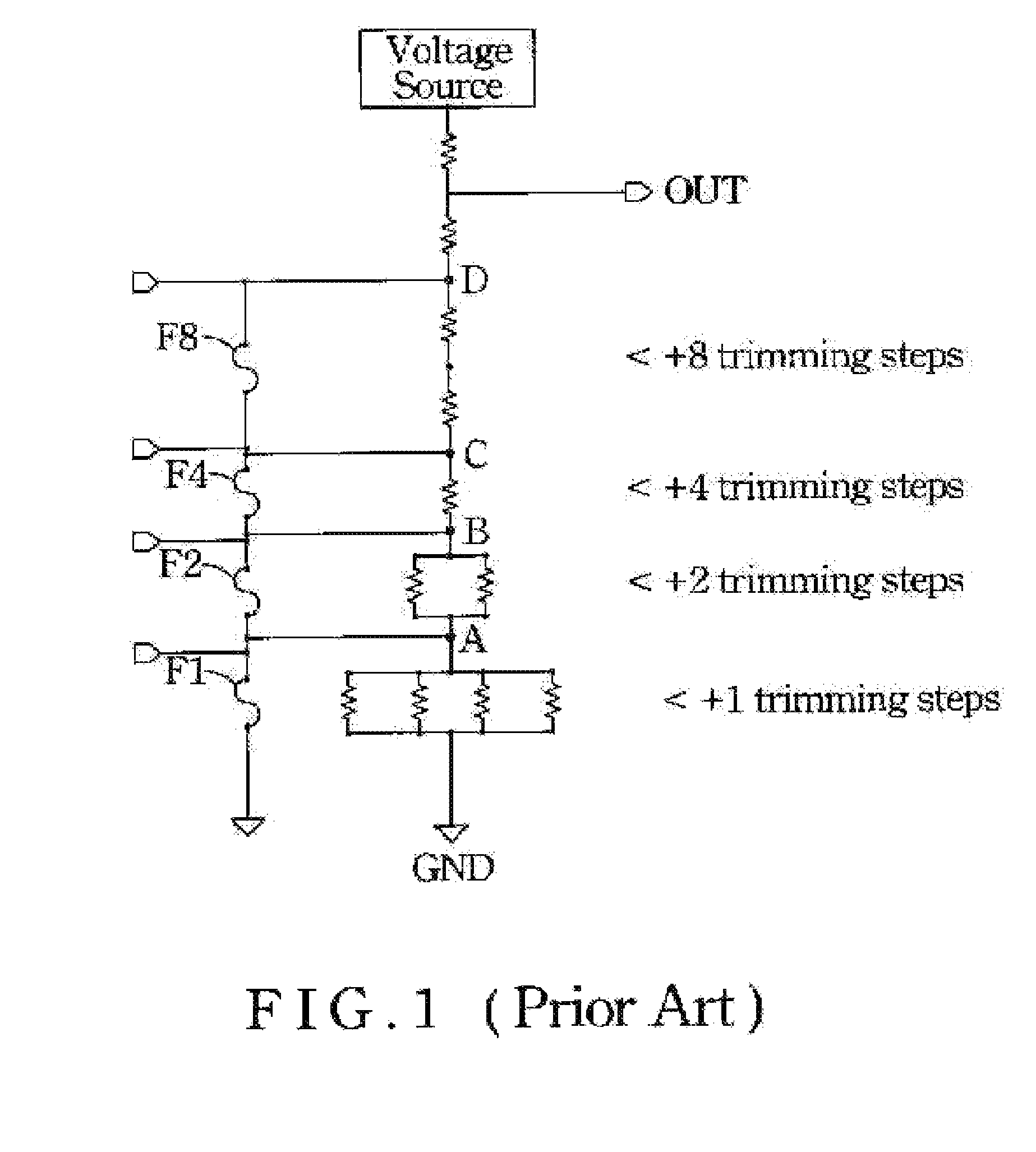
[0021]The binary trimming circuit shown in FIG. 1 provides user one directional adjustment only. This is because the number of trimming steps increase from the ground reference up to the output terminal by a way of 2n, where n is 0, 1, 2 and 3. The output terminal OUT is at the position over the most significant bit. Sometimes, a bidirectional trimming is often preferred to save the testing time. Accordingly, the present invention thus provide another approach, a binary bidirectional trimming circuit to resolve the issues of the prior art.

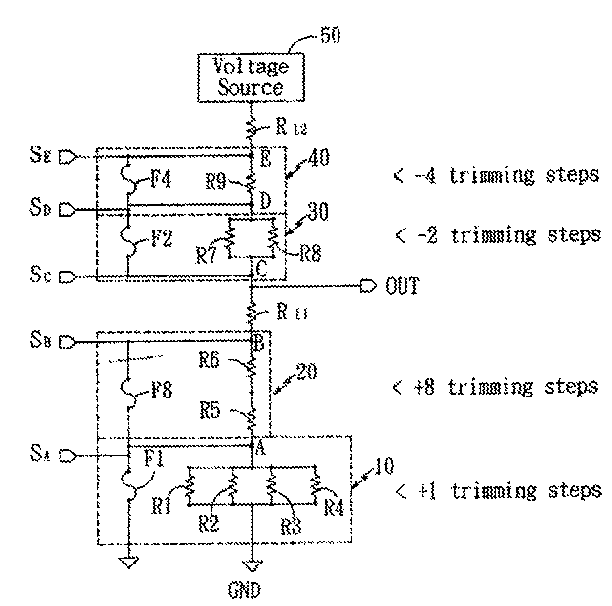
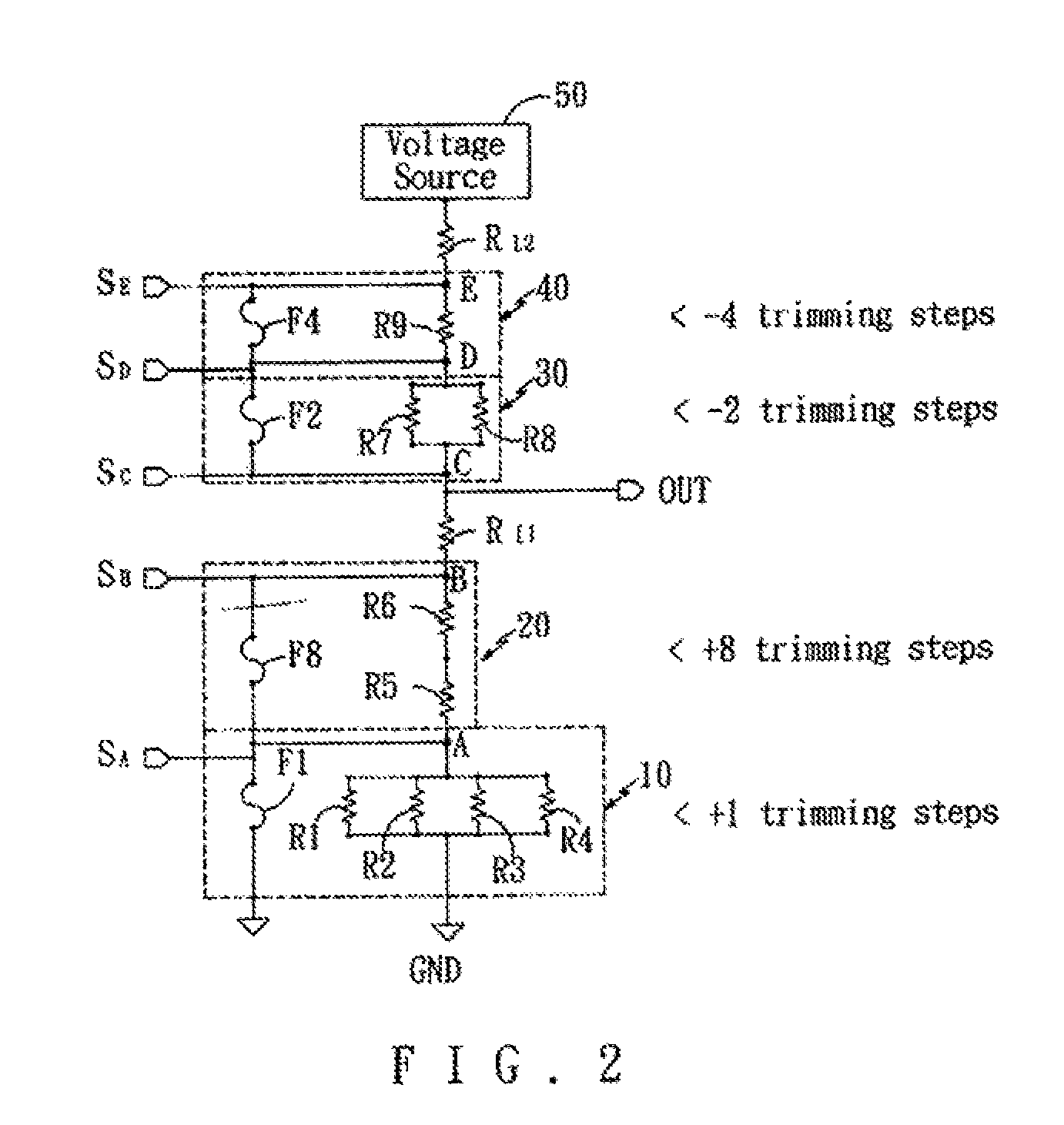
[0022]Referring to FIG. 2, the total number of the resistors are the same as shown in FIG. 1, the permutation of the nodes, and the output terminal OUT are, however, changed. The binary bidirectional trimming circuit is composed of four resistor sets 10, 20, 30, 40 and two loading resistors RL1, RL2, as is shown in FIG. 2. There are: (1) a first resistor set 10 having 4 resistors R1, R2, R3, R4 in parallel connected and a first fuse F1 bridged two ...


PUM


Abstract

A binary bidirectional trimming circuit is disclosed. The trimming circuit includes: a first resistor set having 4 resistors in parallel connected and a first fuse bridged two ends thereto provide one trimming step; a second resistor set having 2 resistors in series connected and a second fuse bridged two ends thereto provide eight trimming steps; a third resistor set having 2 resistors in parallel connected and a third fuse bridged two ends thereto provide two trimming steps; a fourth resistor set having 1 resistor and a fourth fuse bridged two ends thereto provide four trimming steps; a first loading resistor; and a second loading resistor. The first resistor set, second resistor set, first loading resistor, third resistor set, the fourth resistor set, and the second loading resistor are in series connected. The output terminal is located at the nodes of the third resistor set and the first loading resistor so that the trimming steps provided by the third resistor set and the fourth resistor set are opposite to that of the first resistor set and the second resistor set.

Description

BACKGROUND OF THE INVENTION[0001](1) Field of the Invention[0002]The invention relates to a trimming fuse circuit, and more particularly, to a circuit.[0003](2) Description of the Prior Art[0004]Recently, with advance of photolithography technology and etching technology in semiconductor industry, the integrity density of single chip is almost three orders of magnitude than ten years ago. In achievement of such a highly integrated circuit, the advance of semiconductor processes make a great contribution that is second to none, and memory cell repair concept as well as trimming fuse circuit also make a great contribution. During each of semiconductor process, dies on wafer must be precisely processed and precisely controlled, which is a high technology. But even in deep sub-micron era, and even in nanometer era, active elements like MOS, bipolar transistors etc, and passive elements, like resistors, capacitors etc, have some mismatches, which cause yield losses. The one reason is tha...

Claims


Application Information

Patent Timeline
Patent Type & Authority Patents(United States)
IPC IPC(8): H01H37/76H01H85/00
CPCH01C13/02H01C1/16G11C17/18
Inventor KIM, ULADZIMIR
Owner NEOTEC SEMICON
Why Eureka
Try Eureka