
Driving integrated circuit and image display device including the same

a technology of integrated circuits and integrated circuits, applied in the direction of resistance/reactance/impedence, instruments, computing, etc., can solve the problems of low sense voltage output of sense resistors, errors in calibration circuits, and calibration circuits that may not accurately correct the load current of leds, etc., to achieve accurate determination of voltage and constant current

Inactive Publication Date: 2010-11-11
SAMSUNG ELECTRONICS CO LTD
View PDF19 Cites 45 Cited by
  • Summary
  • Abstract
  • Description
  • Claims
  • Application Information

AI Technical Summary

Benefits of technology

[0009]It is yet another feature of an embodiment to provide a driving IC that is adapted to supply a relatively more constant current based on a shorter calibration time to a respective LED, relative to comparable conventional devices.
[0012]It is therefore a separate feature of an embodiment to provide a driving IC that is adapted to more accurately determine a voltage across a sense resistor and to supply a relatively more constant current to a respective LED, relative to comparable conventional devices.

Problems solved by technology

However, since the conventional sense resistor has a resistance value of several ohms (Ω) in order to minimize the power loss of the calibration circuit, the sense voltage output from the sense resistor is low, which induces errors in the calibration circuit.
As a result, the calibration circuit may not precisely correct the load current of the LED.
Moreover, since the sense resistor is directly connected with the LED, the LED may be undesirably turned on while the calibration circuit performs current calibration using a direct resistance sensing method.
Embodiments are therefore directed to driving integrated circuits and image display devices, which substantially overrcome one or more of the problems due to the limitations and disadvantages of the related art.

Method used


Image

  • Driving integrated circuit and image display device including the same
  • Driving integrated circuit and image display device including the same
  • Driving integrated circuit and image display device including the same

Examples


Embodiment Construction

[0052]This application claims priority under 35 U.S.C. §119 to Korean Patent Application No. 10-2009-0040214, filed on 8 May 2009, and to Korean Patent Application No. 10-2009-0070484, filed on 31 Jul. 2009, in the Korean Intellectual Property Office, the disclosures of both of which are incorporated herein by reference.

[0053]The present invention now will be described more fully hereinafter with reference to the accompanying drawings, in which embodiments of the invention are shown. This invention may, however, be embodied in many different forms and should not be construed as limited to the embodiments set forth herein. Rather, these embodiments are provided so that this disclosure will be thorough and complete, and will fully convey the scope of the invention to those skilled in the art. In the drawings, the size and relative sizes of layers and regions may be exaggerated for clarity. Like numbers refer to like elements throughout.

[0054]It will be understood that when an element ...


PUM


Abstract

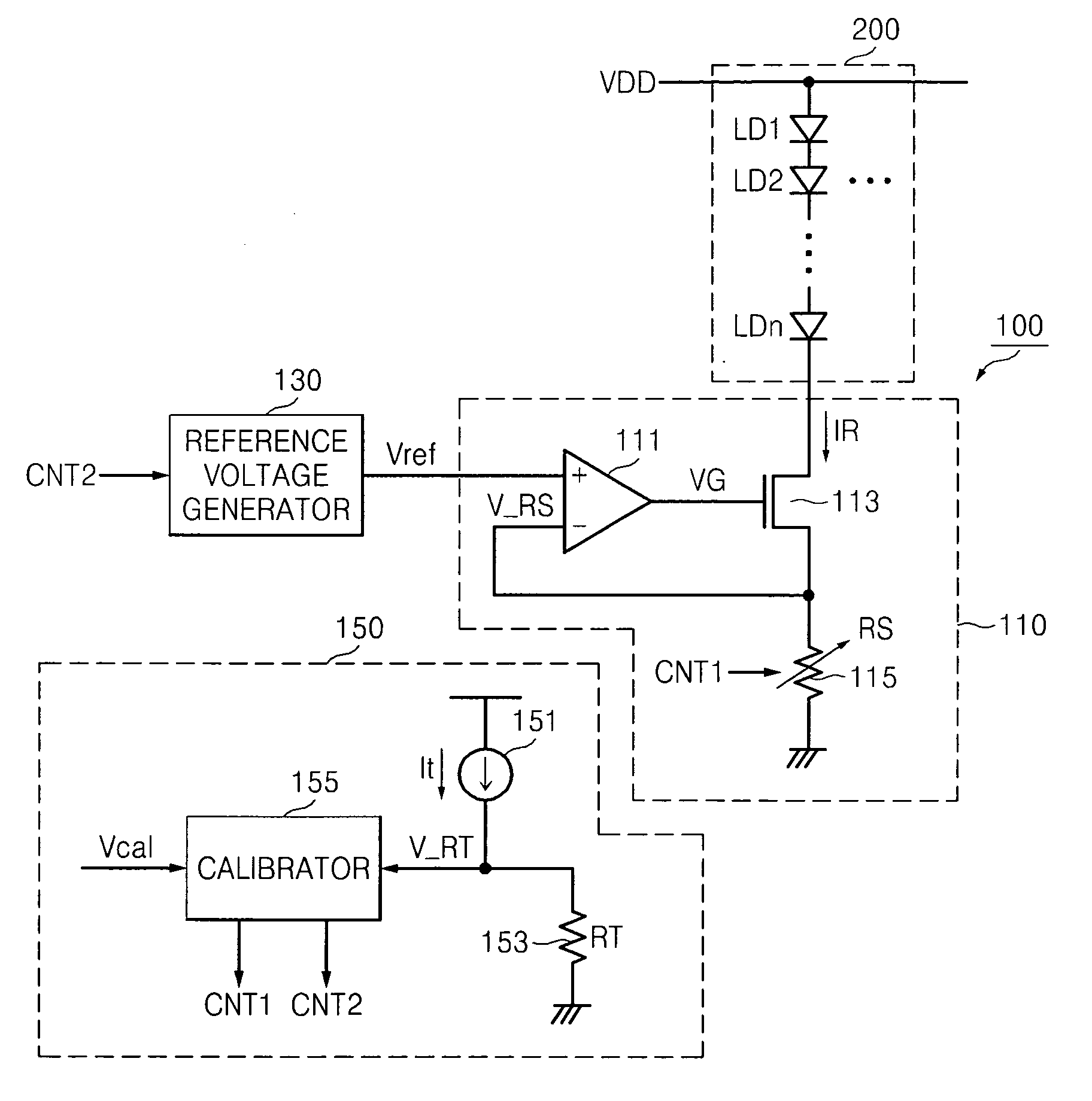
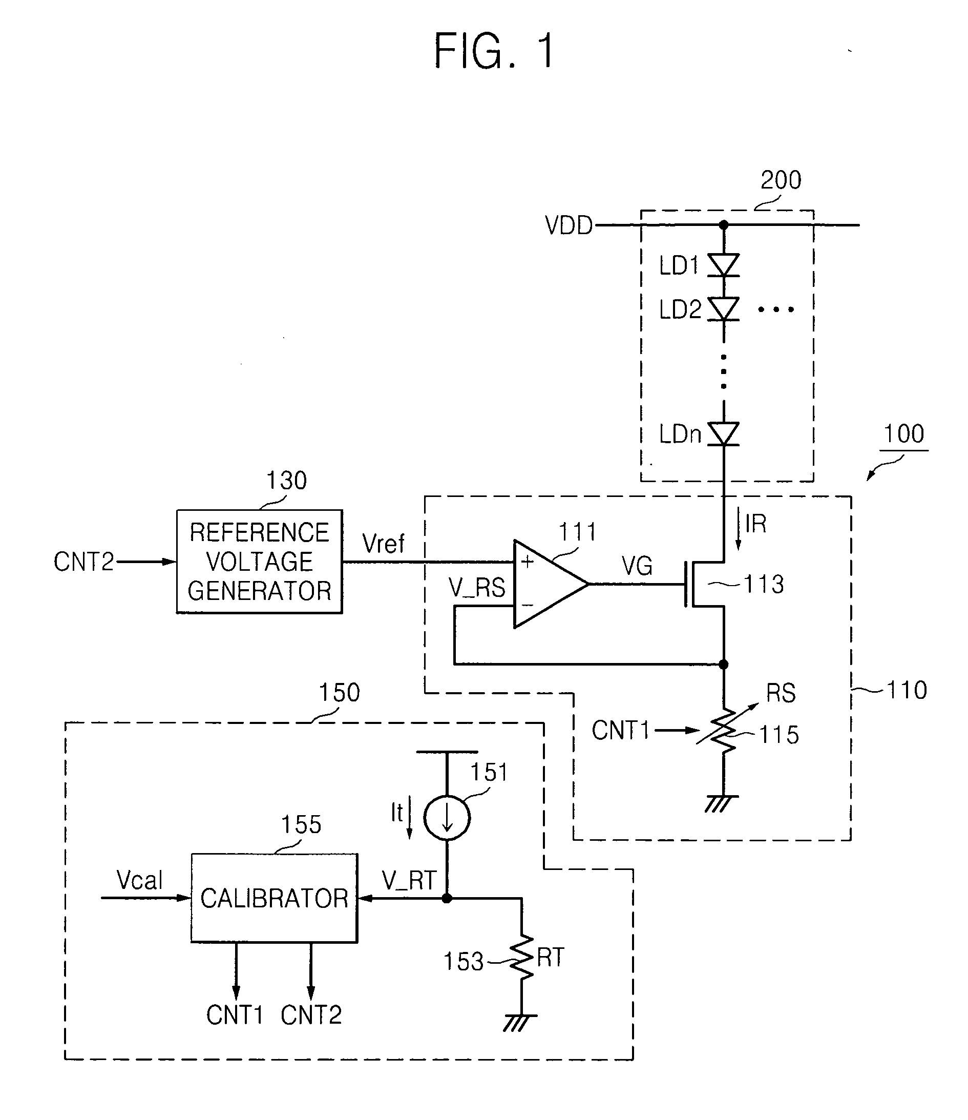
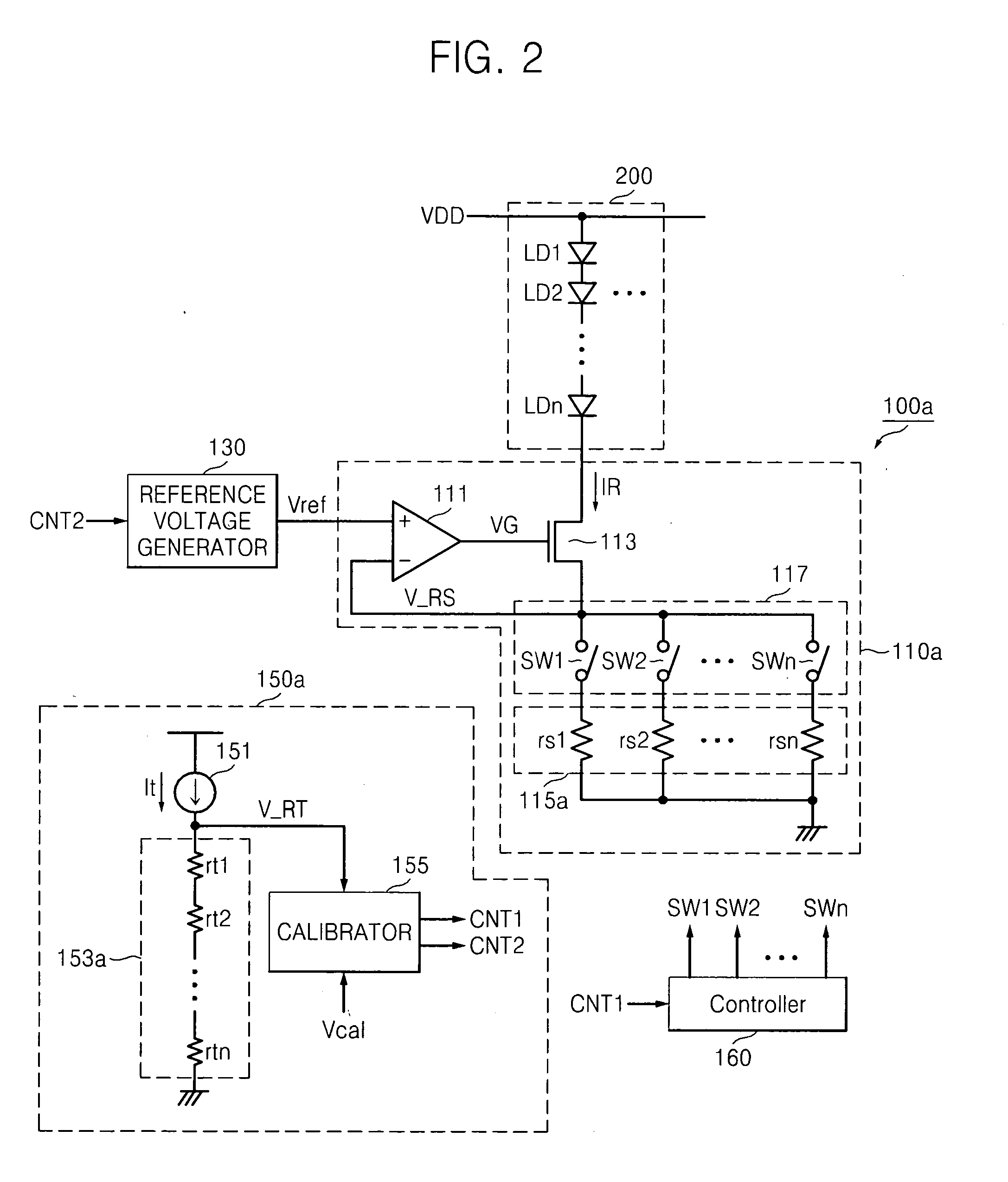
A driving integrated circuit (IC) is provided. The driving IC includes a reference voltage setup circuit configured to output a reference voltage based on a test voltage and a load current control unit comparing a load voltage output from a load resistor with the reference voltage in response to a load current and maintaining the load current constant based on a result of the comparison.

Description

BACKGROUND[0001]1. Field of the Invention[0002]Embodiments relate to a driving integrated circuit (IC), and more particularly, to a driving IC capable of performing current calibration using an indirect sensing method and an image display device including the same.[0003]2. Description of the Related Art[0004]Driving ICs are employed to supply LEDs with a current for enabling the LEDs to emit light. Each LED may emit light having a brightness based on various characteristics of the LED, e.g., an amount of current flowing therethrough, a resistance of a sense resistor employed therewith, temperature, process, etc. Thus, driving ICs used with LEDs require a high-precision load current.[0005]In order to secure the high-precision load current in the driving IC, a calibration circuit is required to compensate for variation of resistance of a sense resistor, for example, connected with an LED, with respect to temperature or processes. The calibration circuit also needs high calibration pre...

Claims


Application Information

Patent Timeline
IPC IPC(8): G06F3/038G01R35/00
CPCG09G2310/0278G09G3/20
Inventor KIM, YONG-HUN
Owner SAMSUNG ELECTRONICS CO LTD
Learn More