Image-forming apparatus having movable tensioner and electrode member that reduce toner scatter

a technology of toner scattering and movable tensioner, which is applied in the field of image-forming apparatuses, can solve the problems that the scattering of toner cannot be controlled, the desired electric field cannot be formed between the image-carrying belt and the electrode plate, etc., and achieve the effect of reducing the scattering of toner

Inactive Publication Date: 2009-09-15
CANON KK
View PDF6 Cites 4 Cited by
  • Summary
  • Abstract
  • Description
  • Claims
  • Application Information

AI Technical Summary

Benefits of technology

[0010]The present invention is directed to an image-forming apparatus capable of reducing toner scattering even when the path taken by an image-carrying belt is changed according to the movement of a tensioner.

Problems solved by technology

The positional relationship between the image-carrying belt and the electrode plates is changed as the path of the image-carrying belt is changed, and as a result, a desired electric field cannot be formed between the image-carrying belt and the electrode plates.
Thus, the scattering of the toner cannot be regulated.

Method used


Image

  • Image-forming apparatus having movable tensioner and electrode member that reduce toner scatter
  • Image-forming apparatus having movable tensioner and electrode member that reduce toner scatter
  • Image-forming apparatus having movable tensioner and electrode member that reduce toner scatter

Examples


first exemplary embodiment

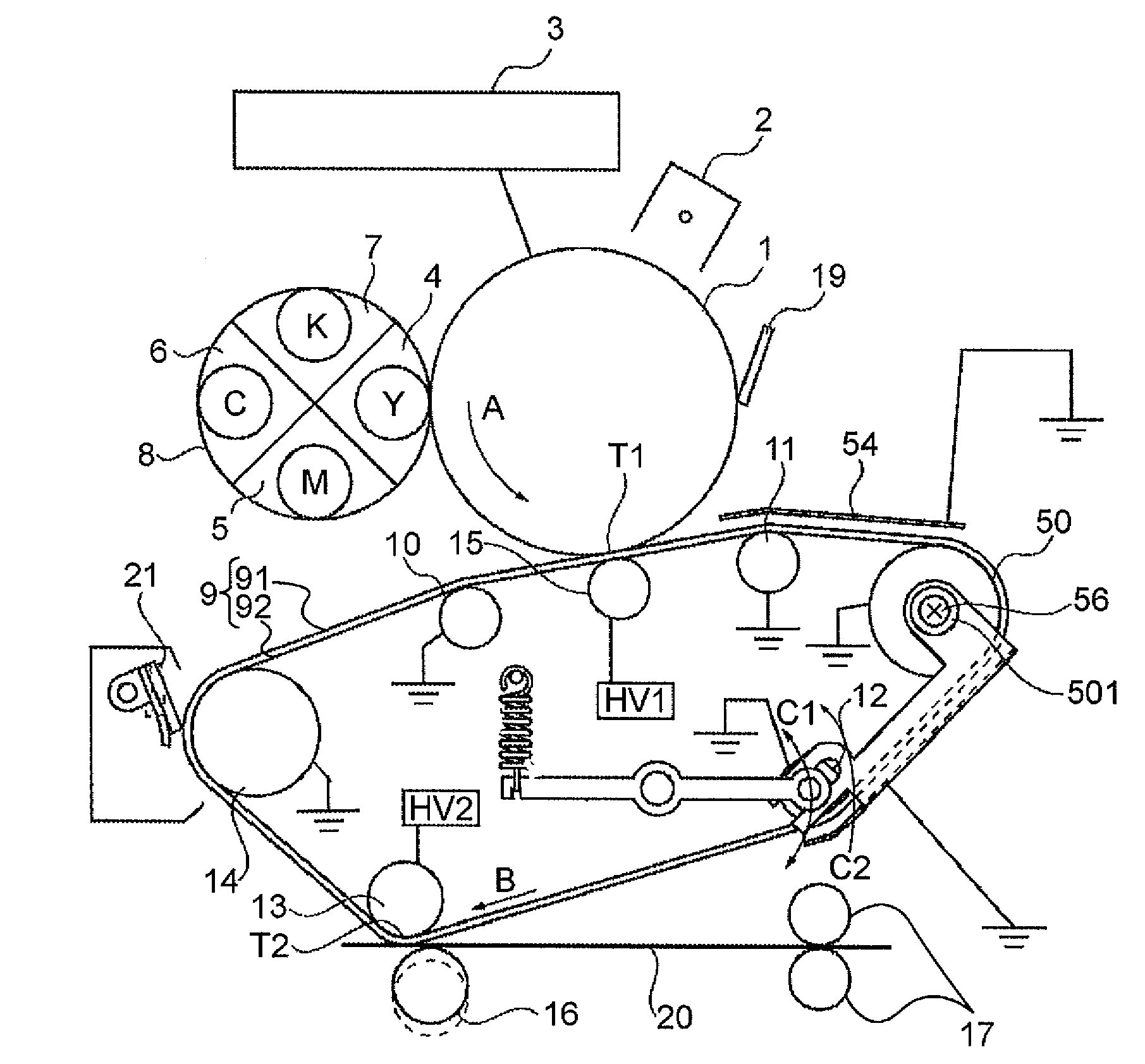
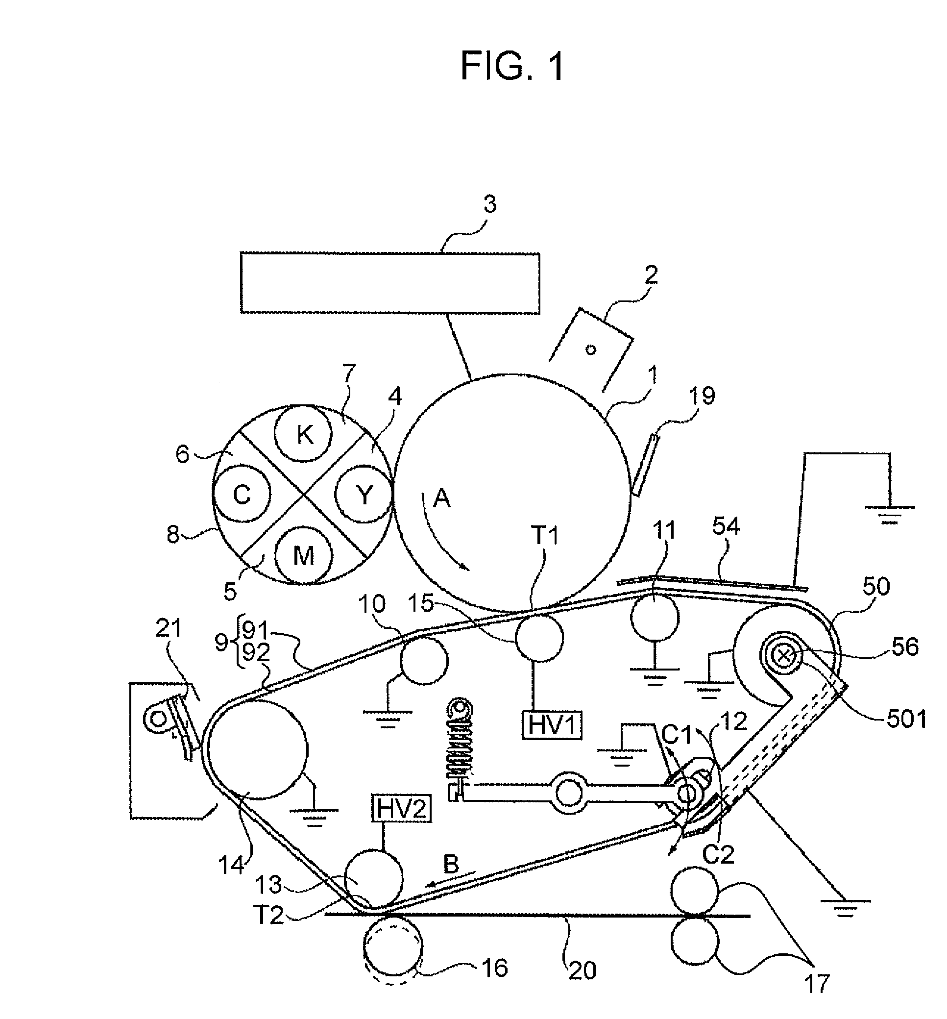
[0029]FIG. 1 illustrates a schematic structure of a color-image-forming apparatus to which the present invention is applied.

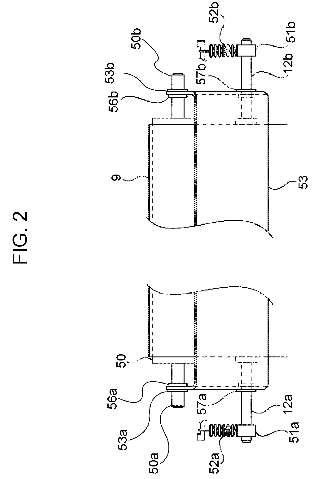
[0030]FIG. 2 illustrates an intermediate transfer belt 9 (described below) and a roller 12 that supports the intermediate transfer belt 9 in detail. The image-forming apparatus according to this exemplary embodiment will now be described with reference to FIGS. 1 and 2.

[0031]A photosensitive drum (image carrier) 1 rotates in the direction of an arrow A shown in FIG. 1, and the surface thereof is negatively charged in a uniform manner by an electrifying unit 2 during the rotation of the photosensitive drum 1. The charged photosensitive drum 1 is exposed to light by an exposing unit 3 that performs exposure on the basis of image information such that electrostatic images corresponding to the image information are formed.

[0032]A developing unit 8 including developing devices 4 to 7 corresponding to colors of yellow (Y), magenta (M), cyan (C), and black (BK), respe...

second exemplary embodiment

[0084]The rollers 11, 50, and 12 shown in FIG. 1 are grounded. In contrast, a bias (+1 to +3 kV) having a polarity opposite to that of the toner is applied to the rollers 11, 50, and 12 of the image-forming apparatus according to this exemplary embodiment shown in FIG. 8 by a power supply HV3.

[0085]When a bias is applied to the roller 11, the potential of the intermediate transfer belt 9 is also raised. However, the potential difference between the roller 11 and the intermediate transfer belt 9 can be further reduced due to the potential-controlling plate 54.

[0086]Thus, the electric field intensity in the vicinity of the contact portion of the intermediate transfer belt 9 and the roller 11 can also be further reduced, and toner scattering can be effectively prevented.

[0087]Therefore, as shown in FIGS. 8 and 9, the potential-controlling plate 53 according to the second exemplary embodiment of the present invention is attached to the apparatus via insulating members 55a and 55b.

[0088...


PUM


Abstract

An image-forming apparatus includes an image-carrying belt that is rotated while carrying toner images on an outer circumferential surface thereof; a movable tensioner applying tension to the image-carrying belt, a position of the tensioner being changed while being in contact with the inner circumferential surface of the image-carrying belt, the tensioner being electrically grounded or a voltage being applied to the tensioner; and an electrode member, a position of the electrode member being changed in conjunction with a change of the position of the tensioner so as to maintain a predetermined distance from the image-carrying belt, the electrode member being electrically grounded or a voltage being applied to the electrode member.

Description

BACKGROUND OF THE INVENTION[0001]1. Field of the Invention[0002]The present invention relates to image-forming apparatuses of an electrophotographic type using intermediate transfer bodies, and in particular, relates to image-forming apparatuses capable of reducing degradation of toner images on intermediate transfer bodies.[0003]2. Description of the Related Art[0004]Recently, intermediate transfer belts (image-carrying belts) have been often used for forming images on various recording media in image-forming apparatuses that form images using electrophotography.[0005]However, when toner images that are transferred onto the intermediate transfer belts reach supporting rollers that support the intermediate transfer belts, the toner on the intermediate transfer belts scatters.[0006]According to Japanese Patent Laid-Open No. 2004-109743, electrode plates to which a predetermined voltage is applied are disposed in the vicinity of a supporting roller such that a desired electric field i...

Claims


Application Information

Patent Timeline
Patent Type & Authority Patents(United States)
IPC IPC(8): G03G15/01
CPCG03G15/1605G03G2215/1614G03G15/1615
Inventor IWATA, HYOE
Owner CANON KK
Why Eureka
Try Eureka