Rotor assembly and method

a technology of rotors and components, applied in the direction of brake discs, mechanical devices, brake types, etc., can solve the problems of prohibitively expensive design, relative weight, and inability to manufacture and assembl

Active Publication Date: 2009-09-29
GM GLOBAL TECH OPERATIONS LLC
View PDF91 Cites 47 Cited by
  • Summary
  • Abstract
  • Description
  • Claims
  • Application Information

AI Technical Summary

Problems solved by technology

Conventional brake rotors are typically composed of cast iron or steel and are therefore relatively heavy.
In the past, such a design was prohibitively expensive to manufacture and assemble and was therefore primarily used for racing applications.

Method used


Image

  • Rotor assembly and method
  • Rotor assembly and method
  • Rotor assembly and method

Examples


Embodiment Construction

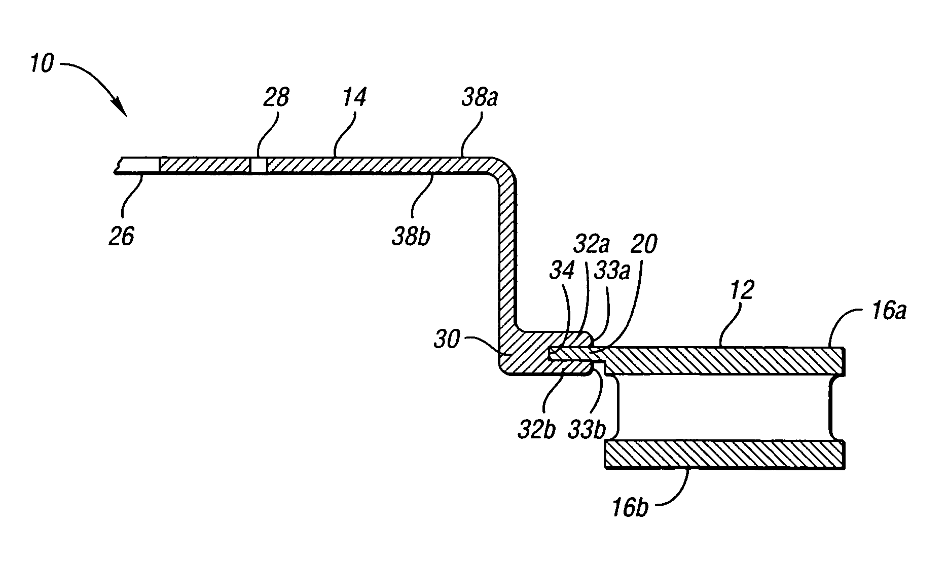
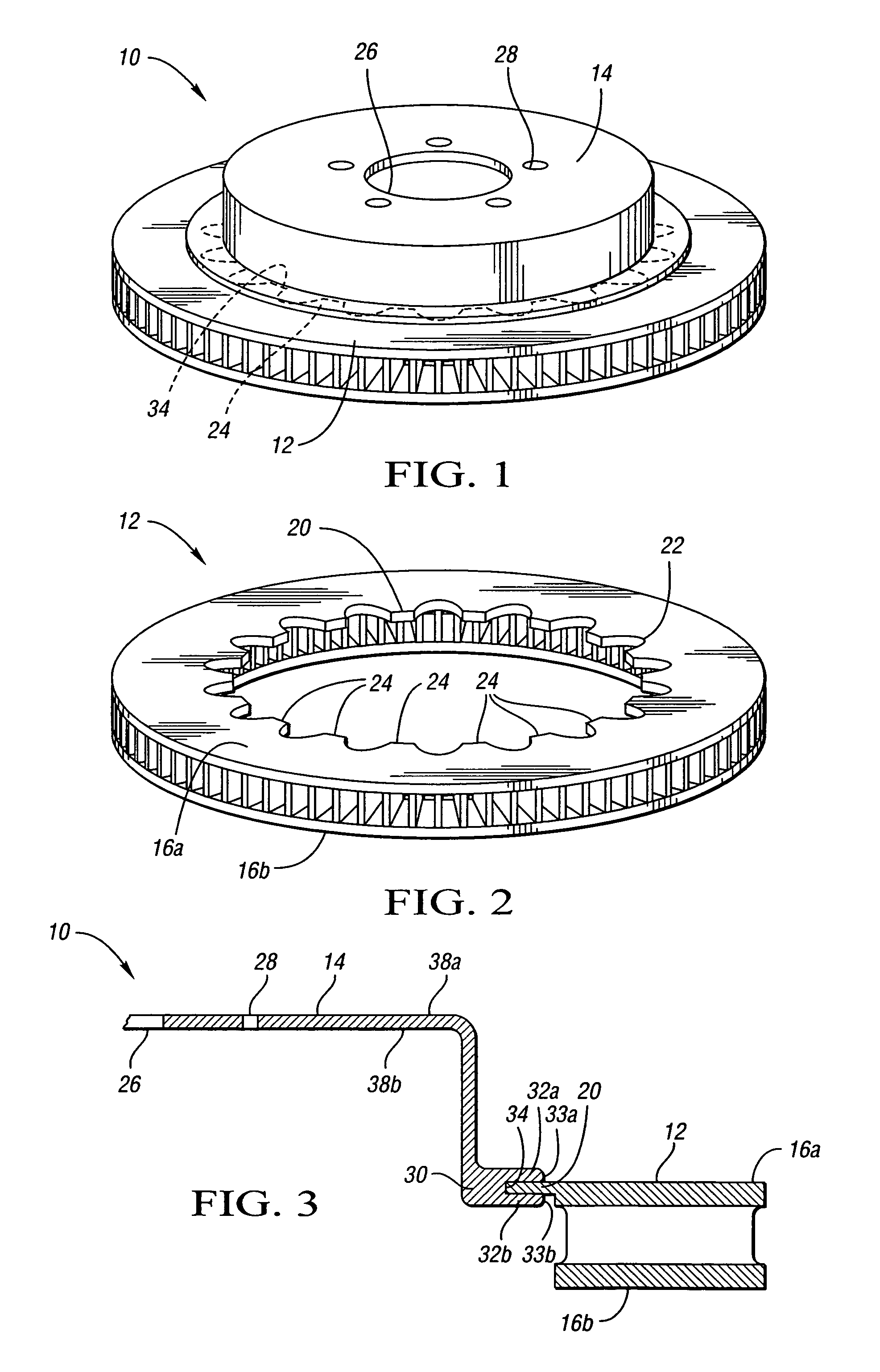
[0012]Referring to the drawings, wherein like reference numbers refer to like components, FIG. 1 shows a perspective view of a brake rotor assembly 10 in accordance with the present invention. The rotor assembly 10 includes a radially outer vented rotor 12 and a radially inner hub section 14 circumscribed by the vented rotor 12. It should be appreciated that the vented rotor 12 is shown for illustrative purposes, and that the present invention also applies to alternate rotor configurations.

[0013]Referring to FIG. 2, the vented rotor 12 is shown in more detail. The vented rotor 12 includes opposing frictional surfaces or cheeks 16a, 16b adapted for engagement by a brake pad (not shown). The rotor 12 has a radially internal rotor flange 20 with an edge 22 having a plurality of rotor teeth 24. The rotor teeth 24 are adapted to engage complementary hub teeth 34 (shown in FIGS. 1 and 3) on the hub section 14 and thereby resist rotation of the rotor 12 relative to the hub section 14.

[0014...


PUM

PropertyMeasurementUnit
densityaaaaaaaaaa
densityaaaaaaaaaa
compressive forceaaaaaaaaaa

Abstract

The apparatus of the present invention provides a brake rotor assembly. The brake rotor assembly includes a generally annular rotor having a frictional surface and a radially inner rotor flange defining a plurality of rotor teeth. The brake rotor assembly also includes a hub section integrally formed onto the rotor. The hub section has a peripheral hub flange configured to engage the plurality of rotor teeth and thereby prevent rotation of the hub section relative to the rotor. The rotor is preferably composed of a first material such as steel or cast iron, and the hub section is preferably composed of a second material such as aluminum or magnesium that is lighter by volume than the first material. Accordingly, the overall weight of the rotor assembly is less than that of a comparable rotor assembly composed entirely of steel or cast iron.

Description

CROSS-REFERENCE TO RELATED APPLICATIONS[0001]This application claims priority to U.S. Provisional Patent Application No. 60 / 740,882 filed on Nov. 30, 2005.TECHNICAL FIELD[0002]The present invention pertains generally to an improved rotor assembly and method for producing a rotor assembly.BACKGROUND OF THE INVENTION[0003]Conventional brake rotors are typically composed of cast iron or steel and are therefore relatively heavy. Accordingly, it is known to make a brake rotor assembly composed of an outer cast iron or steel ring including the friction surface engaged by the brake pad, and an aluminum or magnesium inner disc mounted thereto in order to save weight. In the past, such a design was prohibitively expensive to manufacture and assemble and was therefore primarily used for racing applications.SUMMARY OF THE INVENTION[0004]The brake rotor assembly of the present invention includes a generally annular rotor having a frictional surface and a radially inner rotor flange defining a p...

Claims


Application Information

Patent Timeline
Patent Type & Authority Patents(United States)
IPC IPC(8): F16D65/12
CPCB22D19/00F16D65/12F16D2065/1316F16D2250/0015F16D2065/1344F16D2200/0013F16D2200/003F16D2065/1328
Inventor HANNA, MICHAEL D.KLEBER, RICHARD M.
Owner GM GLOBAL TECH OPERATIONS LLC
Why Eureka
Try Eureka