Retainer for a rotatable tool

a technology of rotatable tools and rotatable tools, which is applied in the direction of slitting machines, flat surface machines, profiling/shaping machines, etc., can solve the problems of machine being taken out of service, uneven wear, and significantly shortening its useful li

Inactive Publication Date: 2009-10-13
THE SOLLAMI COMPANY
View PDF15 Cites 39 Cited by
  • Summary
  • Abstract
  • Description
  • Claims
  • Application Information

AI Technical Summary

Problems solved by technology

If the tool fails to rotate, the tool will wear unevenly and its useful life will be significantly shortened.
When a number of tools on the machine become worn, the machine must be taken out of service and the damaged tools removed and replaced.
If the rotating teeth on the drum encounter a particularly hard substance, such as a rock or large piece of metal, the impact may suddenly stop the rotation of the drum.
It has been found, however, that over a period of time the forward end of the tool holder becomes worn away by a radial flange on the tool as the tool rotates.
The results of the wearing of the forward surface of the tool holder is that the shank of replacement tools fits deeper into the bore of the tool holder and the annular groove on the shank is no longer aligned with the spring pin that retains the tool in the tool holder.
The consequence is that continued rotation of the tool causes the spring pin to be worn away.
As a result, the instance of tool failure, where the tool is lost out of its retainer, occurs more frequently as the tool holders of the machine become worn.

Method used


Image

  • Retainer for a rotatable tool
  • Retainer for a rotatable tool
  • Retainer for a rotatable tool

Examples


Embodiment Construction

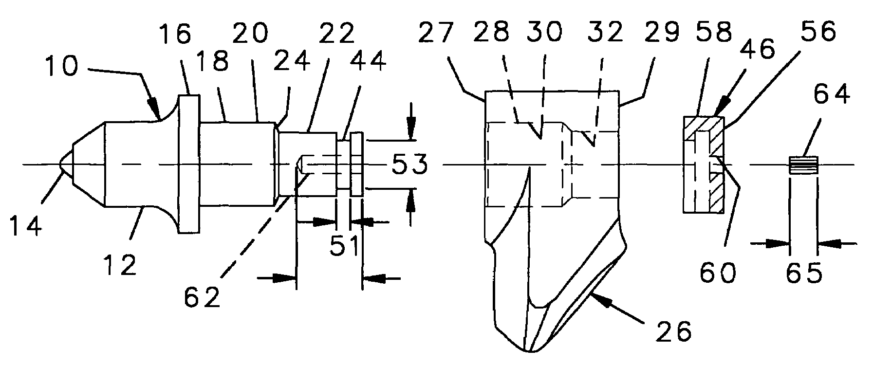
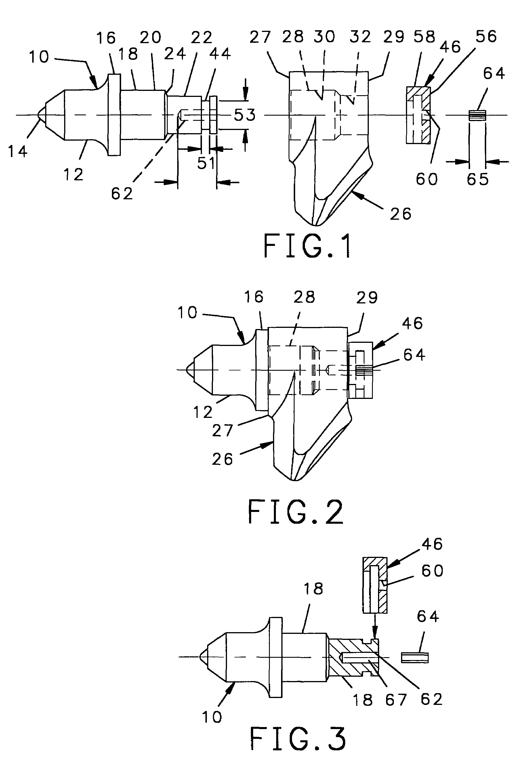
[0029]Referring to FIGS. 1, 2 and 3, a tool 10 has a generally conical forward cutting end 12 at the forward end of which is a hardened tip 14 for cutting up material. Rearward of the forward cutting end 12 is an enlarged diameter radial flange 16 and rearward of the radial flange 16 is an axially aligned generally cylindrical shank 18. The shank 18 may have a single diameter along its entire length, or may have a first large diameter 20 and rearward of the large diameter 20, a second smaller diameter portion 22 with the larger and smaller diameter portions joined by a shoulder 24 as shown.

[0030]The tool 10 is retained in a tool holder 26 having forward surface 27, a rearward surface 29, and extending through the forward and rearward surfaces 27, 29, a transverse bore 28. The bore 28 has first and second inner diameters 30, 32 that are a little larger than the large diameter 20 and small diameter 22 portions respectively, of the shank 18 and are positioned to retain the full length ...


PUM


Abstract

The cylindrical shank of a rotatable tool is retained in the cylindrical bore of a tool holder by a retainer that engages an annular groove on a portion of the shank of the tool that extends outward of the rear surface of the tool holder. The tool has an axial bore in the distal end of the shank. The retainer has a pair of spaced ridges that engage the annular groove on the shank and a panel that extends across the distal end of the shank. The retainer is held in place by a pin extending through the panel and into the bore in the distal end of the shank.

Description

[0001]The present application is a divisional of my application filed Nov. 15, 2004 and assigned Ser. No. 10 / 988,756 now U.S. Pat. No. 7,343,947. The present application relates to rotatable tools mounted on a drum for mulching up large discarded objects such as tree trunks, boat hulls, and the like, to reduce them to chunks of material small enough for recycling or the like.BACKGROUND OF THE INVENTION[0002]Mulching machines for mulching wood and machines for shredding objects such as boat hulls and tree trunks have a rotatable drum with a plurality of cutting tools mounted on the drum. The cutting tools are symmetric about a longitudinal axis and have a tapered forward cutting end for shredding the material and a cylindrical shank that is rotatably mounted in the cylindrical bore of a tool holder on the machine. The tool must be mounted to rotate as the machine operates so that the tapered forward cutting end of the tool wears evenly around its circumference. If the tool fails to r...

Claims


Application Information

Patent Timeline
Patent Type & Authority Patents(United States)
IPC IPC(8): B27G13/00
CPCE21C35/197
Inventor SOLLAMI, PHILLIP A.
Owner THE SOLLAMI COMPANY
Why Eureka
Try Eureka