Plug in pull bar hinge

a technology of pull bar hinge and hinge, which is applied in the field of latches, can solve the problems of being unable to engage and be disengaged, and achieve the effect of reducing the neck

Inactive Publication Date: 2009-10-20
MAXXMAR
View PDF9 Cites 1 Cited by
  • Summary
  • Abstract
  • Description
  • Claims
  • Application Information

AI Technical Summary

Benefits of technology

[0012]Preferably the body and the L-shaped member are both of square shape, and said control bar hinge pin defines a head at its free end, a shoulder adjacent to said L-shaped member, and a reduced neck between said head and said shoulder. Preferably within the hinge opening, the louvre hinge body defines interior flexible flanges interengageable with the reduced neck on the control bar hinge pin. Preferably the concave surface defines an axis which is parallel to but spaced from the hinge opening axis, and prevents the louvre hinge member from twisting. Usefully, the louvres will be formed in section with a generally aerofoil shape and defining a hollow interior, with openings formed in said louvres for receiving said louvre hinge members.

Problems solved by technology

This was primitive, and tended to become disengaged, over time.
This was not possible where the spacings between the connectors on the control bar were already predetermined.

Method used


Image

  • Plug in pull bar hinge
  • Plug in pull bar hinge
  • Plug in pull bar hinge

Examples


Embodiment Construction

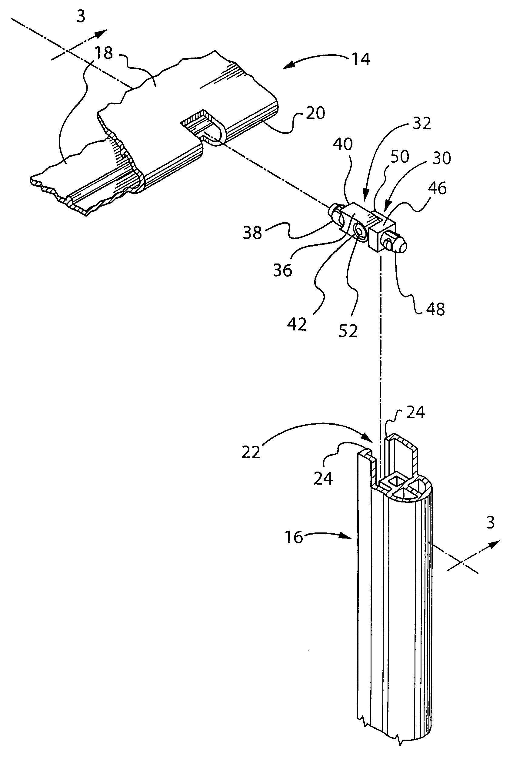
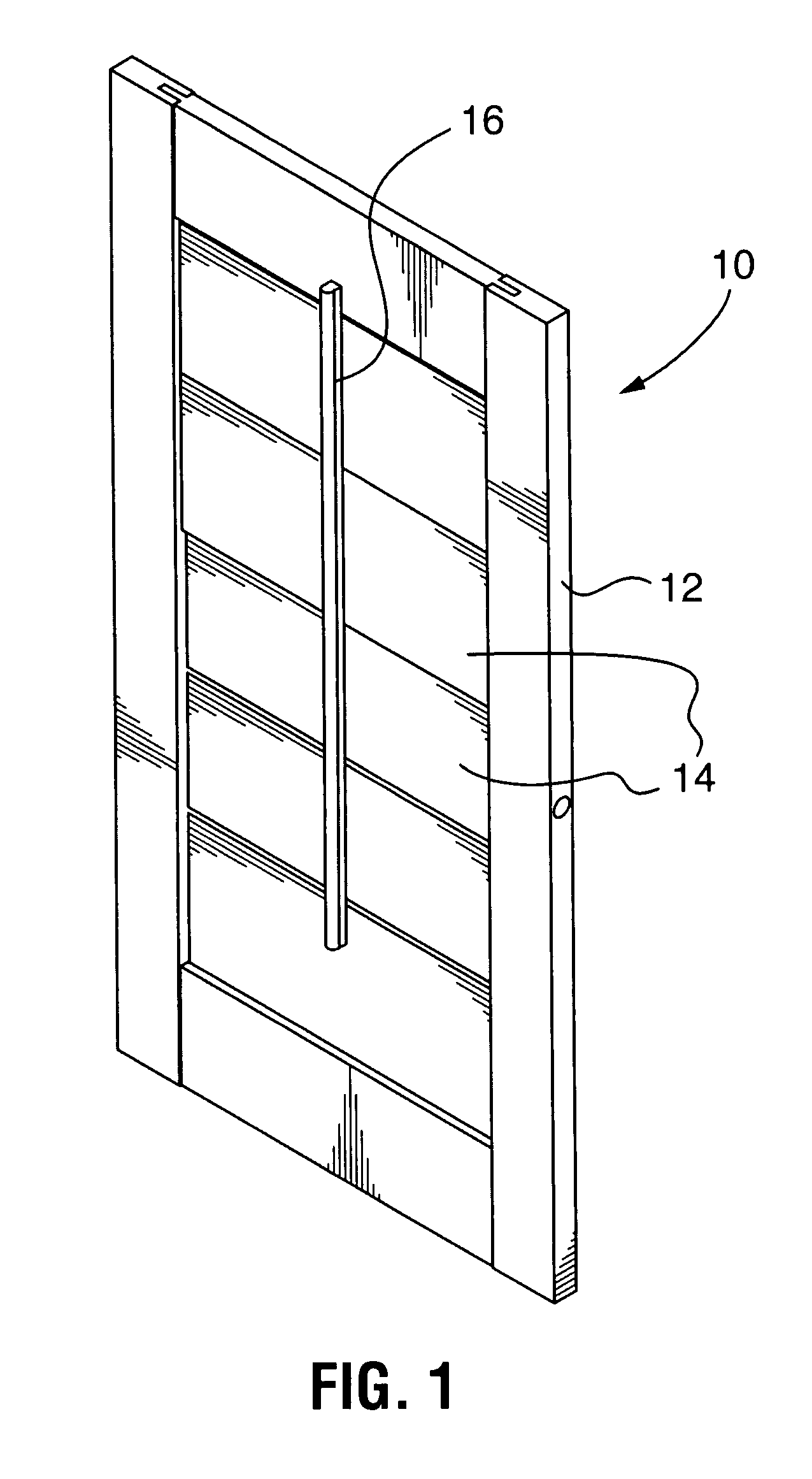
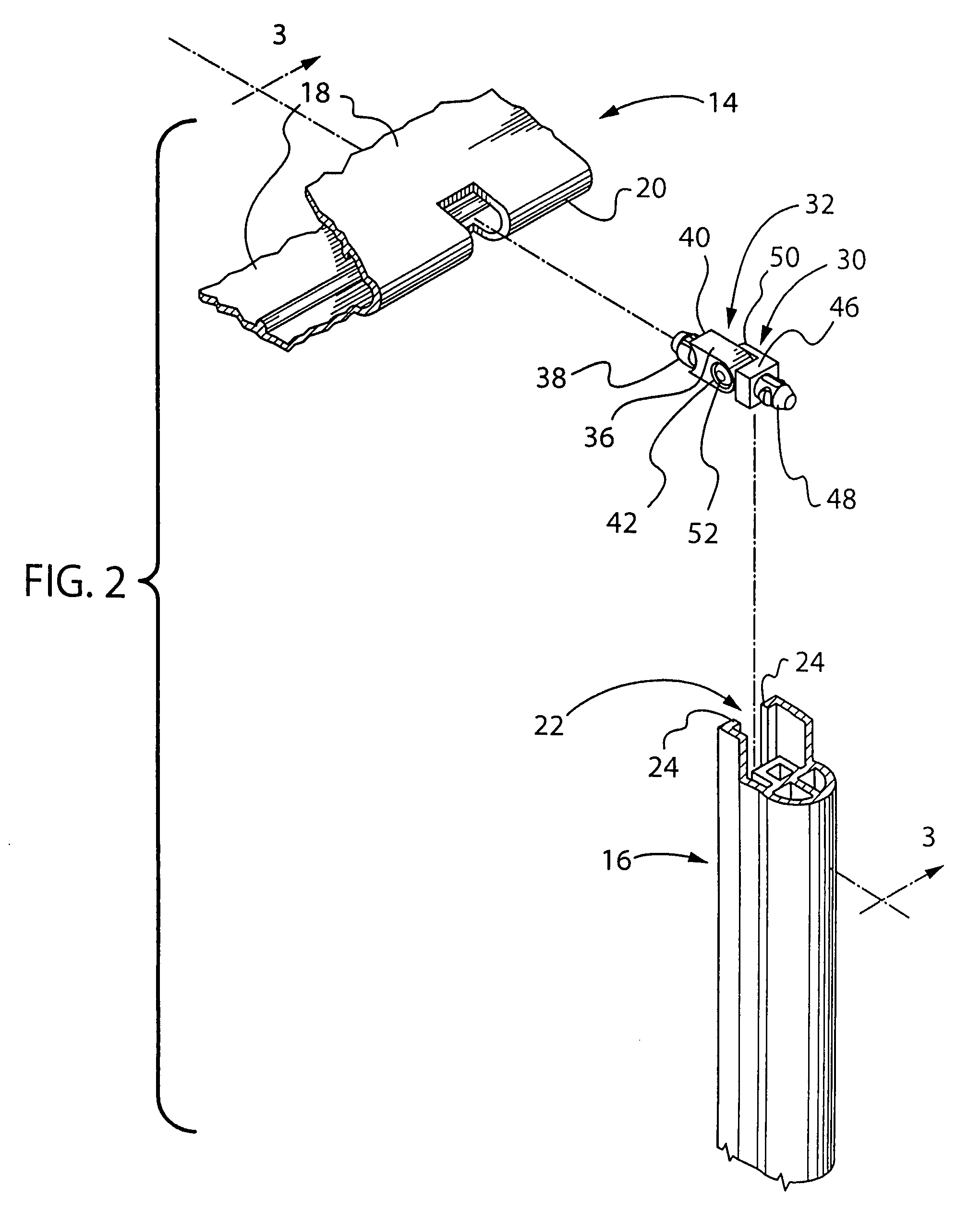
[0022]As already described in general, a shutter (10) consists of a rectangular frame (12), with sides and a top and bottom, louvres (14) rotatably located between the two sides of the frame, and a control bar (16), FIG. 1. Typically the shutter will be hung by hinges (not shown) in a window or a door opening. As such the general construction, and the location and use of shutters is well known.

[0023]The frame (10) may be of any suitable material, synthetic or natural.

[0024]In accordance with one embodiment of the present invention, as illustrated the louvres are of extruded plastic construction and define a hollow interior, FIG. 2.

[0025]However the invention does not exclude shutters with louvres made of other materials, which may be natural or synthetic.

[0026]In this description, as illustrated the louvres (14) in this form of construction define a generally aerofoil shape in section, with upper and lower blade walls (18) of generally convex shape, meeting along edges (20). A hollo...


PUM


Abstract

A shutter having a frame, and having louvres rotatably supported in the frame, and a control bar, for controlling the louvres, and having two-component connectors connecting respective louvres to the control bar, consisting of a louvre hinge member for attachment to a louvre and a control bar hinge member for, and having a louvre hinge body, a louvre plug integral with the louvre hinge body for insertion into a louvre, a concave surface on said louvre hinge body engaging said louvre which prevents twisting, a hinge opening, and having a control bar hinge body, a control bar plug, a control bar hinge pin, cooperating with said hinge opening in said louvre hinge body to provide a hinging action.

Description

FIELD OF THE INVENTION[0001]The invention relates to shutters of the type having a frame, and louvres rotatable in the frame, and a control bar connected to the louvres, for rotating them open and closed, and having connectors connecting the control bar to the louvresBACKGROUND OF THE INVENTION[0002]Shutters for windows and doors usually have a frame, hinged to the window or door opening, and rotatable louvres extending across the frame, from side to side. A control bar is connected to the louvres. Moving the control bar rotates all the louvres. In this way the louvres can be tilted open for light and air, or tilted up or down and closed for privacy.[0003]Shutters have been made in this general pattern for hundreds of years. Usually they were made of wood. The control bar was connected to the louvres, in earlier designs, by a pair of wire staples, one secured to the control bar and the other secured to the louvre.[0004]This was primitive, and tended to become disengaged, over time. ...

Claims


Application Information

Patent Timeline
Patent Type & Authority Patents(United States)
IPC IPC(8): E06B7/086
CPCE06B7/086
Inventor MAROCCO, MARIO M
Owner MAXXMAR
Why Eureka
Try Eureka