Wristwatch with movable movement case
- Summary
- Abstract
- Description
- Claims
- Application Information
AI Technical Summary
Benefits of technology
Problems solved by technology
Method used
Image
Examples
first embodiment
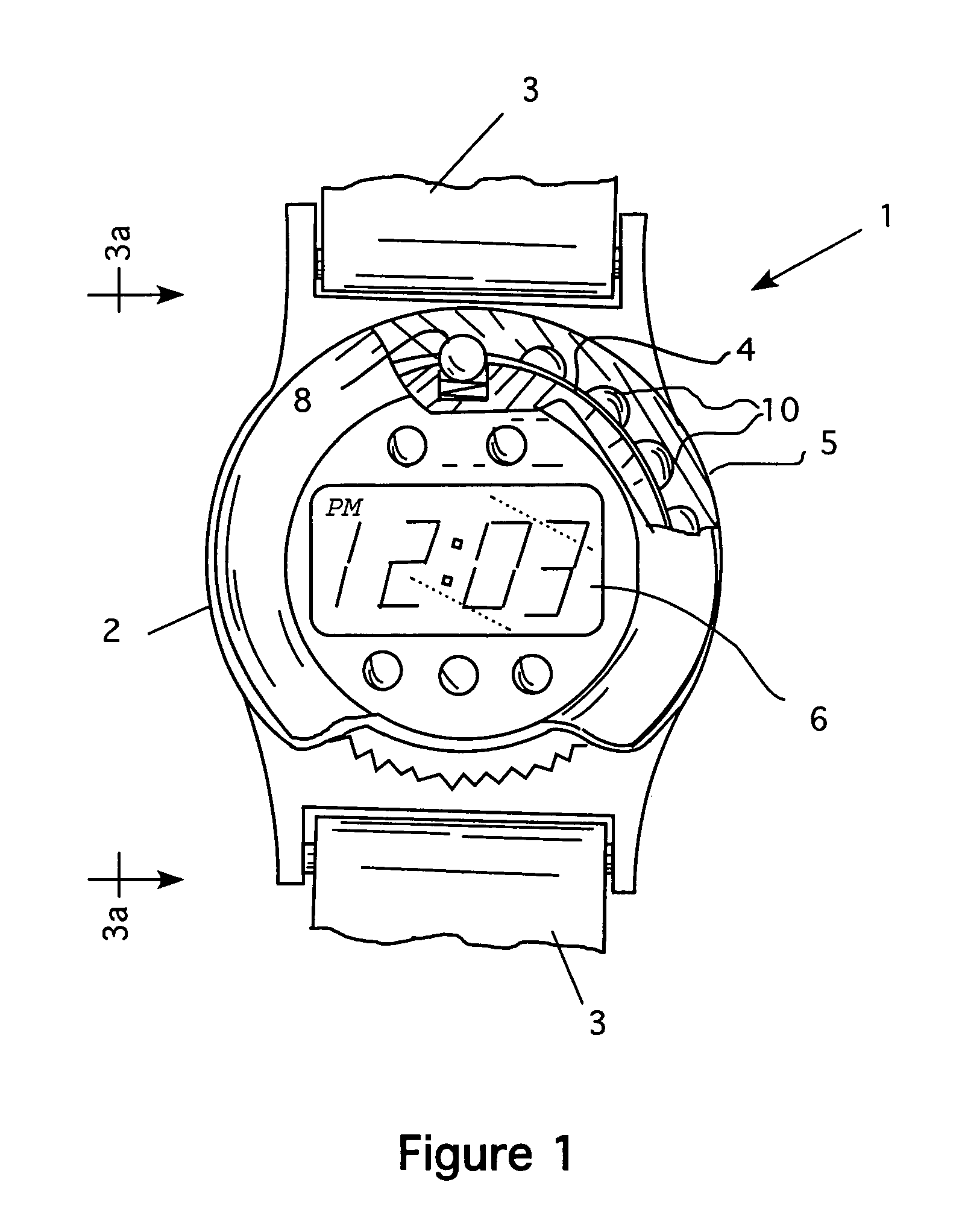
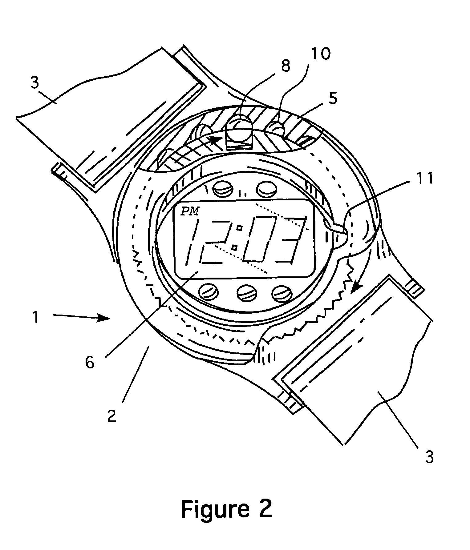
[0057]Referring now to FIGS. 1-4b, the invention is shown. FIG. 1 shows a main body 2 of the watch 1 to which a band 3 is secured. With in this body 2 a turntable 4 rotates on the y-axis. A frame 5 containing the watch mechanism and display 6 is hingeably attached on the turntable by hinge 7 (see FIG. 3a). Thus, the display 6 maybe rotated 360 degrees on the y-axis via said turntable 4. See, e.g., FIG. 2. Moreover, the display can be rotated vertically upon the x-axis by the hinge-mounted frame 5 mounted on said turntable 4. See, e.g., FIGS. 3b and 4b. In this way, the display 6 maybe placed in different viewing fields desired by the wearer. Note that the display maybe left flush in the “standard” viewing position in which the wearer must raise and rotate there wrist as has always been done with all wristwatches up until now. The ability to rotate and or raise the display, on the other hand, allows a user to position the display in a position to be seen in many other positions.
[0058...
second embodiment
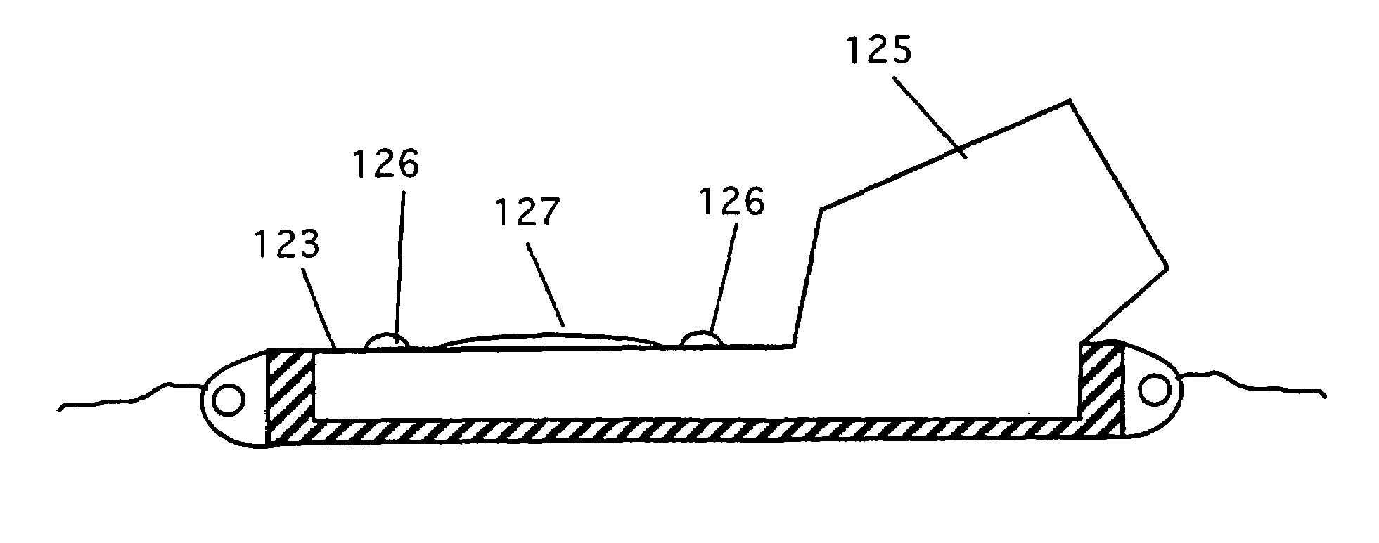
[0060]FIGS. 5a and 5b show a In this embodiment, the turntable and hinged frame (with the bearings and notches) have been eliminated. Here, the watch 20 has a base 21 that has a band 22 attached. The base 21 is shaped as shown with a high center point 23 and a sloped bottom 24 that forms a sloping bowl. The display mechanism 25 is attached to the center high point 23 by a gimbaled bearing 26 that allows the display to freely rotate in the y-axis and in the x-axis to the limits of the sloped base (see FIG. 5b). The display is weighted so that the display continuously rotates into the position most suitable for viewing in whatever position the user's wrist is in. Thus, it is possible for the user to see the watch display while the user's arm is hanging down vertically by the user's side. Subsequently, the watch face rotates to the proper viewing position-and maintains the proper viewing position as the user's wrist is moved, raised, lowered or turned.
[0061]FIGS. 6a, 6b and 7 show yet...
fifth embodiment
[0064]FIGS. 9 and 10 show the invention. Here, the watch 50 is shown is a top view in FIG. 9. The watch has a case 51 with a display 52 and a band 53. FIG. 10 shows that the display 52 extends above the case. The extra height accommodates a side display 56 as shown. Two buttons are placed on the case 51 as shown. Button “A”54 is used to turn on the display on the face of the watch as shown in FIG. 9. Button “B”55 is used to shift the display from the face to the side display. In this way, a user can quickly change the display as desired for the most convenient way to see the display.
PUM
 Abstract
Description
Claims
Application Information
 - R&D
- Intellectual Property
- Life Sciences
- Materials
- Tech Scout
- Unparalleled Data Quality
- Higher Quality Content
- 60% Fewer Hallucinations
Browse by: Latest US Patents, China's latest patents, Technical Efficacy Thesaurus, Application Domain, Technology Topic, Popular Technical Reports.
© 2025 PatSnap. All rights reserved.Legal|Privacy policy|Modern Slavery Act Transparency Statement|Sitemap|About US| Contact US: help@patsnap.com


