Rollover determination apparatus for vehicles

a technology for determining apparatus and vehicles, which is applied in the direction of process and machine control, instruments, pedestrian/occupant safety arrangements, etc., can solve the problem of inability to determine whether the vehicle will roll, and achieve the effect of simplifying the structure and achieving a higher degree of reliability

Active Publication Date: 2005-04-14
NEXGEN CONTROL SYST LLC
View PDF14 Cites 38 Cited by
  • Summary
  • Abstract
  • Description
  • Claims
  • Application Information

AI Technical Summary

Benefits of technology

[0007] The present invention is made in order to solve the above-mentioned problem, and it is therefore an object of the present invention to provide a simple and flexible rollover determination apparatus for vehicles that can quickly and correctly determine whether a vehicle will roll over.
[0009] Therefore, since the rollover determination apparatus in accordance with the present invention determines whether the vehicle will roll over by using at least the roll angular velocity of the vehicle about the longitudinal axis extending lengthwise through the vehicle and the upward or downward acceleration in the upward or downward direction of the vehicle, the rollover determination apparatus can distinguish between side crashes and rollover accidents more correctly and can finely determine whether the vehicle will roll over with a higher degree of reliability even when a rollover accident accompanied by a large lateral acceleration occurs. In addition, the structure of the rollover determination apparatus in accordance with the present invention can be simplified.

Problems solved by technology

A problem with the prior art determination method disclosed by above-mentioned patent reference 1 is that since the method determines whether a vehicle will roll over by using the following three factors: the lateral acceleration, roll angular velocity, and roll angle of the vehicle, it is impossible to determine whether the vehicle will roll over when the lateral acceleration does not occur in coincidence with the occurrence of the roll angular velocity, or it is erroneously determined that the vehicle will roll over when such an accident as a side crash actually occurs.

Method used


Image

  • Rollover determination apparatus for vehicles
  • Rollover determination apparatus for vehicles
  • Rollover determination apparatus for vehicles

Examples


embodiment 1

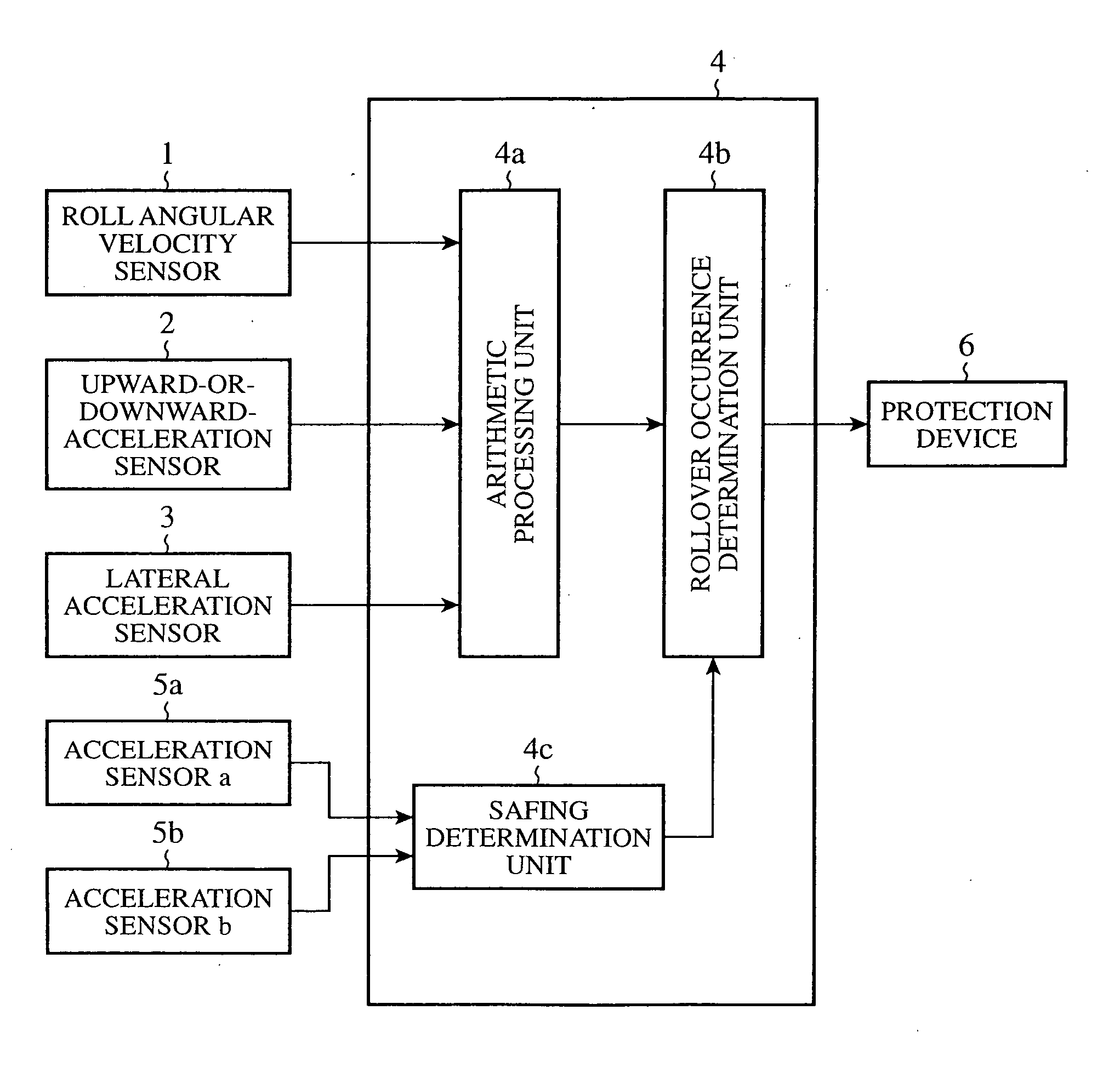
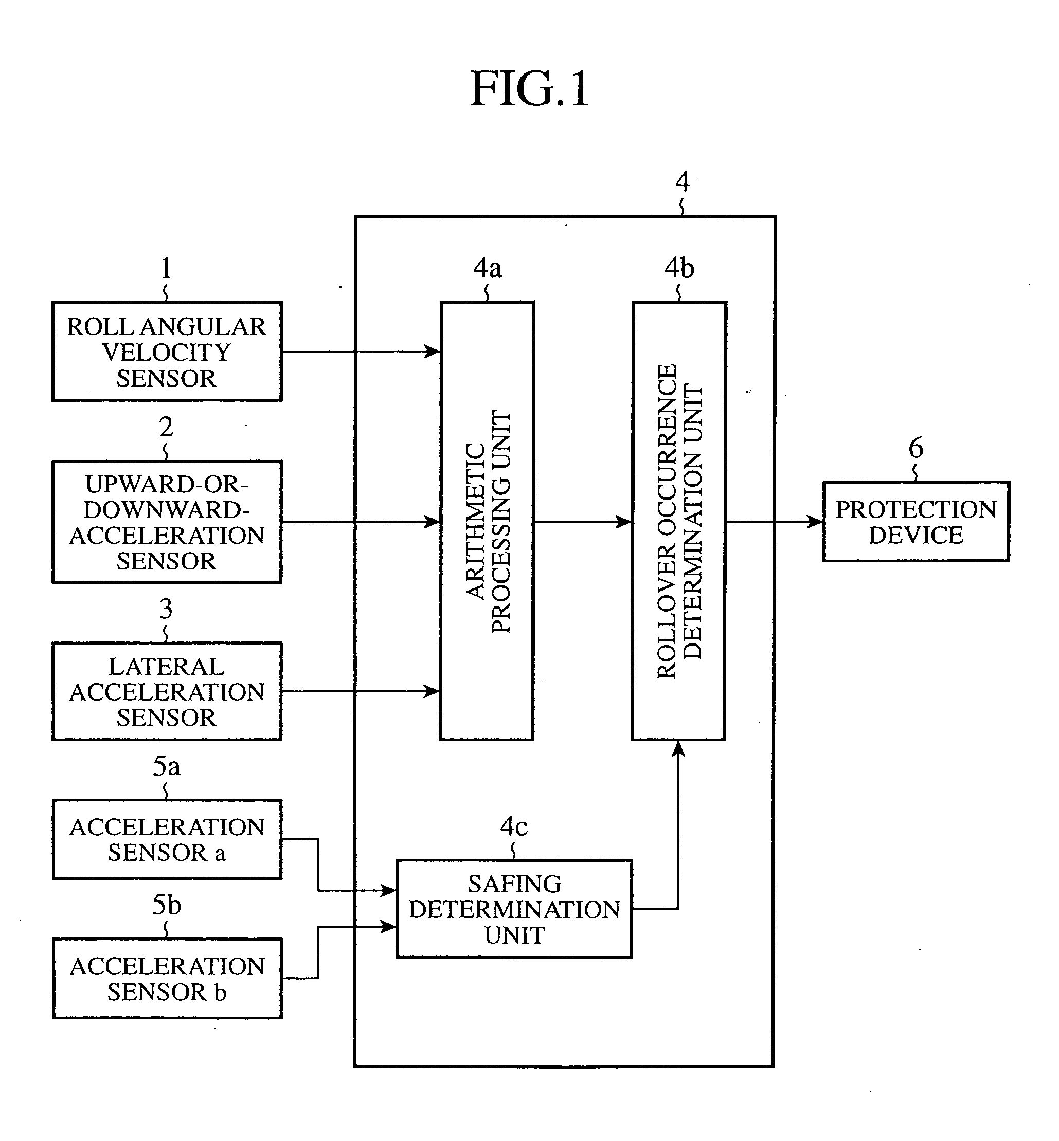
[0025]FIG. 1 is a functional block diagram showing the whole of a rollover determination apparatus for vehicles in accordance with embodiment 1 of the present invention. As shown in FIG. 1, a determination unit is provided with a roll angular velocity sensor 1 provided as a roll angular velocity detecting means, for detecting, as a roll angular velocity, a rotational angular velocity (i.e., a roll rate) of a vehicle about a longitudinal axis extending lengthwise through the vehicle, an upward-or-downward-acceleration sensor 2 provided as an upward-or-downward-acceleration detecting means, for detecting, as an upward or downward acceleration, an acceleration of the vehicle in an upward or downward direction of the vehicle, and a lateral acceleration sensor 3 provided as a lateral acceleration detecting means, for detecting, as a lateral acceleration, an acceleration of the vehicle in a lateral direction of the vehicle, on an input side thereof.

[0026] The determination unit 4 perform...

embodiment 2

[0058]FIG. 7 shows an example of the internal structure of a determination unit of a rollover determination apparatus for vehicles in accordance with embodiment 2 of the present invention, and is a functional block diagram showing a case where addition determination equations are used as determination equations used for determining whether a vehicle will roll over. The determination unit 4 is provided with a first addition unit 12 for carrying out addition of the roll angular velocity Rr of the vehicle detected by a roll angular velocity sensor 1 and the upward or downward acceleration Gz of the vehicle detected by an upward-or-downward-acceleration sensor 2, a second addition unit 14 for carrying out addition of the roll angular velocity Rr, the upward or downward acceleration Gz, and the roll angle Ra of the vehicle, a third addition unit 16 for carrying out addition of the roll angular velocity Rr and the roll angle Ra, and a fourth addition unit 18 for carrying out addition of t...

embodiment 3

[0068]FIG. 8 shows an example of the internal structure of a determination unit of a rollover determination apparatus for vehicles in accordance with embodiment 3 of the present invention, and is a functional block diagram showing the determination unit which uses multiplication determination equations according to above-mentioned embodiment 1 and addition determination equations according to above-mentioned embodiment 2 as determination equations used for determining whether a vehicle will roll over. The determination unit 4 is provided with a first multiplication unit 11 for carrying out multiplication of the roll angular velocity Rr of the vehicle detected by a roll angular velocity sensor 1 and the upward or downward acceleration Gz of the vehicle detected by an upward-or-downward-acceleration sensor 2, a first addition unit 12 for carrying out addition of the roll angular velocity Rr and the upward or downward acceleration Gz, a second multiplication unit 13 for carrying out mu...


PUM


Abstract

A rollover determination apparatus for vehicles includes a roll-angular-velocity sensor (1) for detecting, as a roll angular velocity, the rotational angular velocity of a vehicle about a longitudinal axis extending lengthwise through the vehicle, an upward-or-downward-acceleration sensor (2) for detecting, as an upward or downward acceleration, an acceleration in an upward or downward direction of the vehicle, an arithmetic processing unit (4a) for carrying out arithmetic processing on both the roll angular velocity detected by the roll-angular-velocity sensor (1) and the upward or downward acceleration detected by the upward-or-downward-acceleration sensor (2), and a rollover occurrence determining unit (4b) for determining whether the vehicle will roll over based on a processing result of the arithmetic processing unit (4a).

Description

BACKGROUND OF THE INVENTION [0001] 1. Field of the Invention [0002] The present invention relates to a rollover determination apparatus for determining whether a vehicle will roll over (or turn over) at proper timing. [0003] 2. Description of Related Art [0004] Conventionally, there has been provided a method of determining whether a vehicle will roll over based on a two-dimensional map of the roll angle and roll angular velocity of the vehicle, as one of the most general rollover determination techniques. In accordance with this rollover determination method, if the roll angular velocity of the vehicle is very large or rapidly increases when the vehicle accidentally has a rollover, the timing of determination of whether the vehicle will roll over becomes late. In order to solve this problem, there has been provided a method of classifying the type of the occurrence of rollover according to the acceleration of the vehicle detected by acceleration sensors (of Y-axis and / or Z-axis), a...

Claims


Application Information

Patent Timeline
Patent Type & Authority Applications(United States)
IPC IPC(8): B60R16/02B60R21/00B60R21/01B60R21/013B60R21/0132B60R21/13B60R21/16B60W30/04B60W40/10B60W50/00
CPCB60R21/0132B60R2021/0018B60R2021/01327B60W2050/0026B60W40/11B60W40/112B60W40/114B60W30/04
Inventor SUZUKI, RYOUTAROUINOUE, SATORUNAKAMOTO, MASAHIROTOKUNAGA, TAKASHI
Owner NEXGEN CONTROL SYST LLC
Why Eureka
Try Eureka