Silicon Steel Plate Used to Form a Stator of a Motor

a technology of silicon steel plate and stator, which is applied in the direction of dynamo-electric machines, magnetic circuits characterised by magnetic materials, and magnetic circuit shapes/forms/construction. it can solve the problems of limited motor space, reduced rotor size, and inability to use large-size silicon steel plates b>9/b>, so as to enhance coupling strength, enhance the structural strength of silicon steel plate, and increase the winding space of silicon steel plate

Inactive Publication Date: 2018-06-07
SUNONWEALTH ELECTRIC MACHINE IND
View PDF2 Cites 2 Cited by
  • Summary
  • Abstract
  • Description
  • Claims
  • Application Information

AI Technical Summary

Benefits of technology

[0014]The magnetic yoke ring has an inner periphery and an outer periphery, the pole portion has a width, and the maximal width of the magnetic yoke ring between the inner and outer peripheries is larger than or equal to a half of the width of the pole portion. In this arrangement, the structural strength of the silicon steel plate can be enhanced.
[0015]The pole portion has a width, the boost portion has

Problems solved by technology

In an occasion where a larger torque is required but the available motor space is limited (such as in a drone), the large-size silicon steel plate 9 cannot be used.
As such, the size of the rotor needs to be reduced, which raises many design issues of the motor.
Additionally,

Method used


Image

  • Silicon Steel Plate Used to Form a Stator of a Motor
  • Silicon Steel Plate Used to Form a Stator of a Motor
  • Silicon Steel Plate Used to Form a Stator of a Motor

Examples


first embodiment

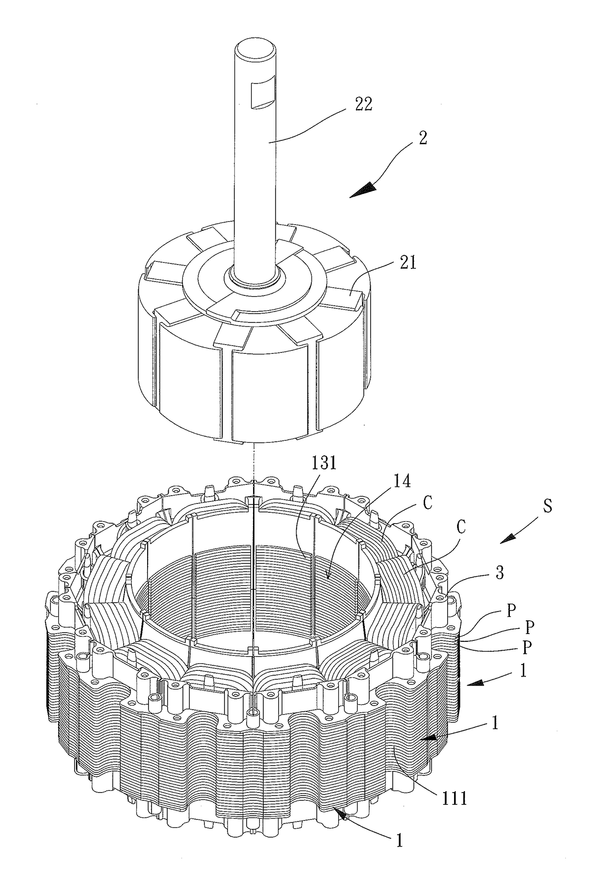
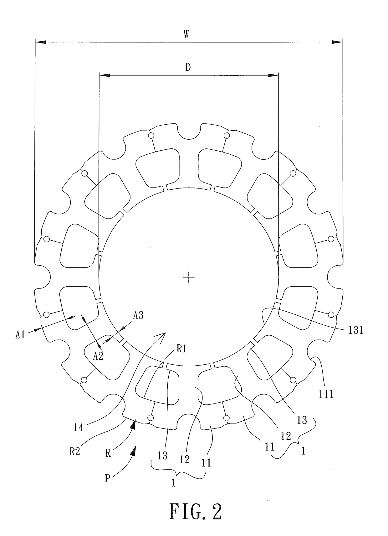
[0026]FIGS. 2 and 3 show a silicon steel plate P used to form a stator of a motor according to the invention. The silicon steel plate P includes a plurality of interconnected magnetic pole units 1. Each magnetic pole unit 1 includes a magnetic yoke portion 11, a pole portion 12 and a boost portion 13. The magnetic yoke portion 11, the pole portion 12 and the boost portion 13 can be integrally formed together or can be connected to each other by any structures or methods. The invention is not limited to either option.

[0027]Specifically, the magnetic yoke portions 11 of the magnetic pole units 1 are connected to form a magnetic yoke ring R. The quantity of the pole portions 12 of the silicon steel plate P may be a multiple of 3, and is preferably 12 at least. The boost portion 13 includes an inner face 131 that increases the magnetically conductive area of the pole portion 12. The inner faces 131 of the boost portions 13 are annularly arranged to form a receiving hole 14, and a magnet...

second embodiment

[0034]FIG. 7 shows a silicon steel plate P′ used to form a stator of a motor according to the invention. The silicon steel plate P′ includes a plurality of interconnected magnetic pole units 5. Each magnetic pole unit 5 includes a magnetic yoke portion 51, a pole portion 52 and a boost portion 53. The pole portion 52 connects the magnetic yoke portion 51 with the boost portion 53. The magnetic yoke portions 51 of the magnetic pole units 5 are connected to form a magnetic yoke ring R. In this embodiment, the magnetic yoke portions 51 of the magnetic pole units 5 can be integrally formed together rather than being bent into the annular shape. In FIG. 7, the broken lines are used to distinguish each magnetic yoke portion 51 from other magnetic yoke portions 51 for illustration purpose. In another embodiment, the magnetic yoke portions 51 of the magnetic pole units 5 can also be arranged in a line and then are bent into the annular shape.

[0035]The inner periphery R1 of the magnetic yoke...


PUM


Abstract

A silicon steel plate used to form a stator of a motor is disclosed. The silicon steel plate includes a plurality of magnetic pole units. Each of the plurality of magnetic pole units includes a magnetic yoke portion, a pole portion and a boost portion. The magnetic yoke portions of the plurality of magnetic pole units are connected as a magnetic yoke ring. The boost portion includes an inner face, and the inner faces of the boost portions of the plurality of magnetic pole units form a receiving hole. The receiving hole has a maximal diameter, the silicon steel plate has a maximal diameter, and a ratio of the maximal diameter of the receiving hole to the maximal diameter of the silicon steel plate is 0.54-0.84.

Description

CROSS REFERENCE TO RELATED APPLICATIONS[0001]The application claims the benefit of Taiwan application serial No. 105139984, filed on Dec. 2, 2016, and the contents of which are incorporated herein by reference.BACKGROUND OF THE INVENTION1. Field of the Invention[0002]The present invention generally relates to a motor component and, more particularly, to a silicon steel plate used to form a stator of a motor.2. Description of the Related Art[0003]FIG. 1 shows a conventional silicon steel plate 9 of a stator of a motor. The silicon steel plate 9 includes a magnetic yoke ring 91. The magnetic yoke ring 91 can be mounted to a base of the motor (not shown). The silicon steel plate 9 further includes a plurality of magnetic poles 92 on an inner periphery thereof. The magnetic poles 92 are annularly spaced from each other in even intervals. At least one coil C may be wound around the magnetic poles 92. A boost portion 93 is arranged at an inner end of each magnetic pole 92 facing the centr...

Claims


Application Information

Patent Timeline
IPC IPC(8): H02K1/14H02K1/02
CPCH02K1/146H02K1/02H02K2213/03H02K1/2773H02K2201/03
Inventor HORNG, ALEXWANG, CHI-MINLIU, KU-LING
Owner SUNONWEALTH ELECTRIC MACHINE IND
Why Eureka
Try Eureka