Mouse trap having a triggering plate

Inactive Publication Date: 2009-10-27
HUANG CHANG HSIU
View PDF91 Cites 14 Cited by
  • Summary
  • Abstract
  • Description
  • Claims
  • Application Information

AI Technical Summary

Benefits of technology

[0011]The primary object of the present invention is to provide a mouse trap ha

Problems solved by technology

The caught mouse is hard to escape.

Method used


Image

  • Mouse trap having a triggering plate
  • Mouse trap having a triggering plate
  • Mouse trap having a triggering plate

Examples


Embodiment Construction

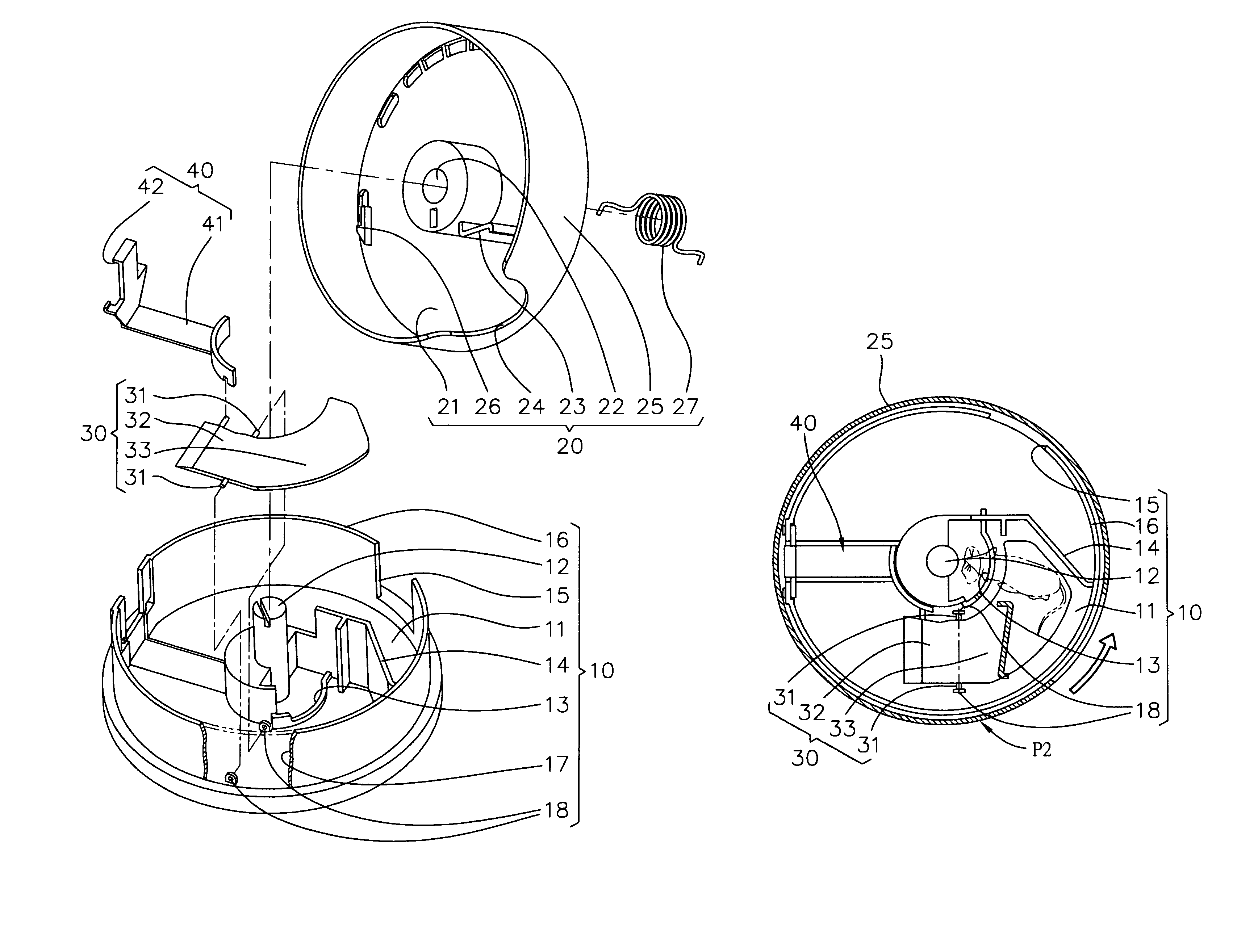
[0027]Referring to FIGS. 6, 7, and 10A, the present invention relates to a mouse trap having a triggering plate. It mainly includes a stationary base 10, rotatable cover 20, triggering plate 30, and a connecting rod assembly 40.

[0028]With regard to this stationary base 10, it has a circular bottom 11, a central shaft 12, central bait housing 13, a first stopper 14, a first opening 15, a fixed outer wall 16, a first receiving portion 17, and a pair of pivoting seats 18. The central bait housing 13 is secured on a middle part of this circular bottom 11. The central shaft 12 is extending upwards from the central bait housing 13. The fixed outer wall 16 is disposed on an outer edge of the circular bottom 11.

[0029]About this rotatable cover 20, it has a circular cover 21, a central shaft hole 22, a second stopper 23, a second opening 24, a rotatable outer wall 25, a locking portion 26 and a torque generator 27. The function of the central shaft hole 22 is to pivot with the central shaft ...


PUM


Abstract

A mouse trap having a triggering plate is disclosed. It mainly includes a stationary base, rotatable cover, triggering plate, and a connecting rod assembly. When a mouse presses down this rear plate portion of the triggering plate, this rear plate portion moves down accordingly. It simultaneously lifts up a linking portion of the connecting rod assembly. Then, it will activate this rotatable cover to rotate from an opening position to a close position for avoiding a caught mouse escaping out. Besides, this invention's triggering sensibility is extremely high. It can trap a mouse that just tries to eat the bait. Plus, the caught mouse is hard to escape.

Description

FIELD OF THE INVENTION[0001]The present invention relates to a mouse trap, especially to a mouse trap having a triggering plate. About this invention, the triggering sensibility is extremely high. It can trap a mouse that just tries to eat the bait. Plus, the caught mouse is hard to escape.DESCRIPTION OF THE PRIOR ART[0002]Referring to FIGS. 1, 2, 3, 4, 5A and 5B, the traditional mouse trap includes a stationary part 50, a rotatable cap 60, and a linking assembly 70.[0003]This stationary part 50 has a central bait container 51, a first blocker 52, and a first hole 53. The function of this central bait container 51 is to install the mouse bait.[0004]The rotatable cap 60 has a second blocker 61, a second hole 62, a locking part 63, and a torque spring 64. The function of this torque spring 64 is to make the rotatable cap 60 rotating from an open position P1 to a close position P2.[0005]The linking assembly 70 has a pair of pivoting parts 71 and a lifting part 72. These two pivoting pa...

Claims


Application Information

Patent Timeline
IPC IPC(8): A01M23/00A01M23/10A01M23/24A01M23/26
CPCA01M23/16A01M23/24A01M23/18
Inventor HUANG, CHANG-HSIU
Owner HUANG CHANG HSIU
Why Eureka
Try Eureka